Mechanical vs. Hydraulic Tube Expansion: Engineering Guide
Mechanical vs. Hydraulic Tube Expansion: Engineering Guide
Steve
2026-10-09
Mechanical vs. Hydraulic Tube Expansion: Engineering Guide for Heat Exchanger Manufacturing
In the manufacturing of air-cooled condensers, unit coolers, and industrial heat exchangers, tube expansion is the critical process determining both thermal efficiency and structural integrity.
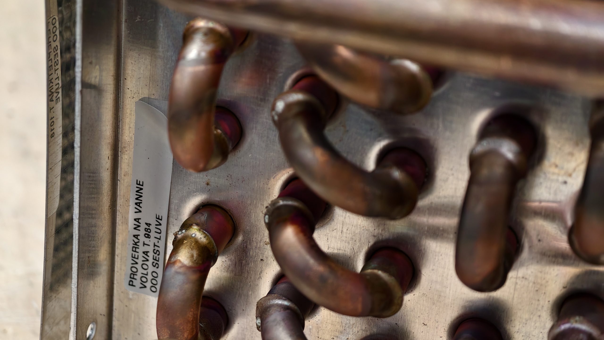
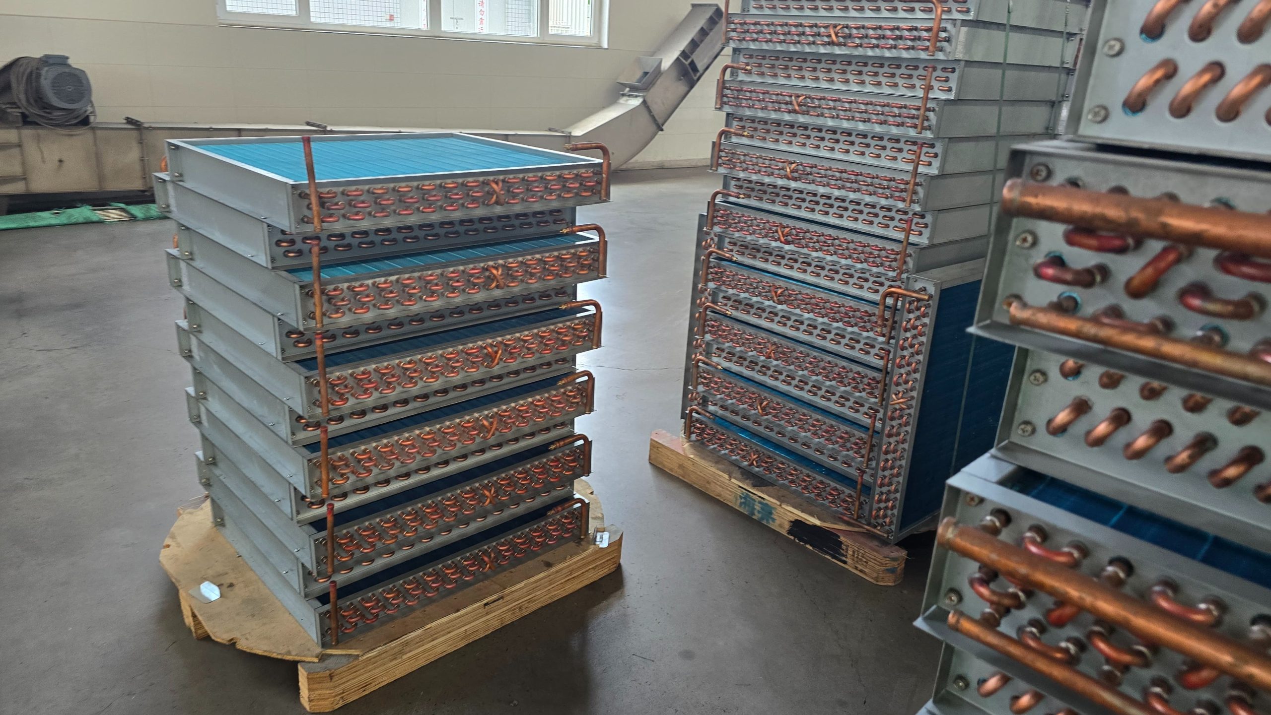
After seamless tubes (copper, aluminum, or stainless steel) are laced into stamped aluminum fin stacks, they must undergo controlled plastic deformation. This forces the tube’s outer wall into micron-level contact with the fin collars, eliminating air gaps and minimizing thermal contact resistance.
In modern production lines, two primary technologies dominate: Mechanical Tube Expansion (bullet/mandrel driven) and Hydraulic Tube Expansion (high-pressure fluid driven).
This guide breaks down their mechanical principles, tube wall stress behavior, coil geometry limitations, and equipment selection criteria.
1. Operating Principles and Mechanical Dynamics
While both processes aim to achieve zero-gap contact between the tube OD and the fin collar ID, their mechanical energy transfer methods differ radically:
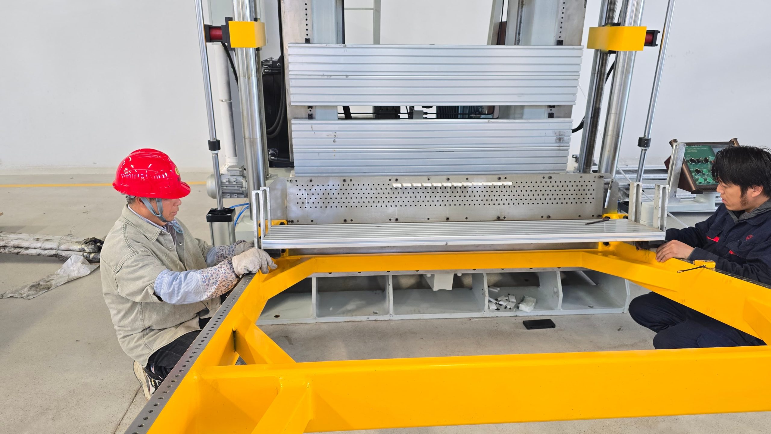
Mechanical Expansion (Mandrel / Bullet Driven): A tungsten carbide bullet (mandrel) attached to a rigid push/pull rod is driven through the tube interior. The bullet’s outer diameter is oversized relative to the tube ID, mechanically pushing the tube wall outward through direct physical displacement.
Hydraulic Expansion (Direct Fluid Pressure): High-pressure liquid (typically treated water) is injected into the sealed inner tube cavity. Under ultra-high hydrostatic pressure (typically 100 to 300 MPa), the tube wall expands uniformly outward omnidirectionally until it yields against the fin matrix.
Selecting the optimal expander configuration depends directly on coil dimensions, tube metallurgies, and production capacity requirements:
(1) Commercial Refrigeration & Short Coils (Length < 1.5 m)
Recommended Setup: Vertical or Horizontal Mechanical Tube Expander.
Engineering Rationale: Short coil lengths experience minimal axial tube wall stretching. Mechanical expanders offer high cycle speeds, low initial capital investment, and straightforward mechanical maintenance for standard copper/aluminum configurations.
(2) Large Cold Room Air Coolers & Industrial Evaporators (Length 2.0 m – 6.0 m+)
Engineering Rationale: Pushing mechanical rods through long tubes causes rod buckling and severe tube thinning near the entry point. Hydraulic expansion applies uniform radial pressure across the entire tube length simultaneously, ensuring consistent thermal contact from end to end.
Designing an efficient heat exchanger coil production line requires precise alignment between product dimensions and machine specifications.
To help our engineering team evaluate your coil design and provide an accurate technical proposal and quotation, please include the following parameters in your inquiry:
RFQ Technical Information Checklist:
Tube Specifications:
Material (Copper / Aluminum / Stainless Steel / Titanium)
Tube Outer Diameter (e.g., 7 mm, 9.52 mm, 12.7 mm, 15.88 mm) & Wall Thickness
Available Shop Floor Footprint and Overhead Height Clearance
Power Supply Standard (e.g., 380V / 50Hz / 3-Phase or custom) & Compressed Air Supply Pressure
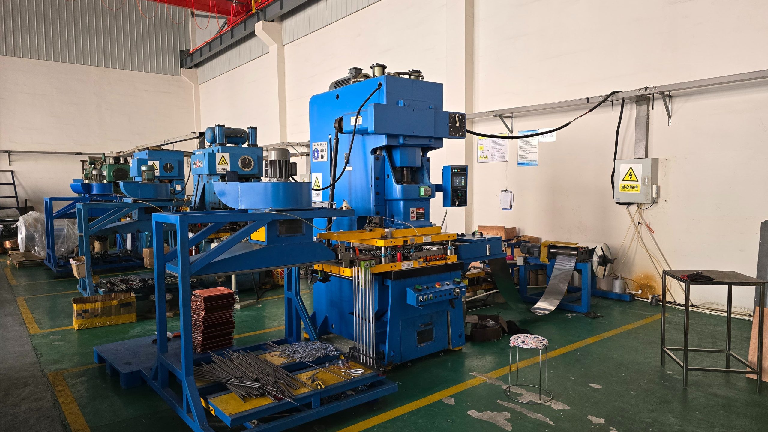
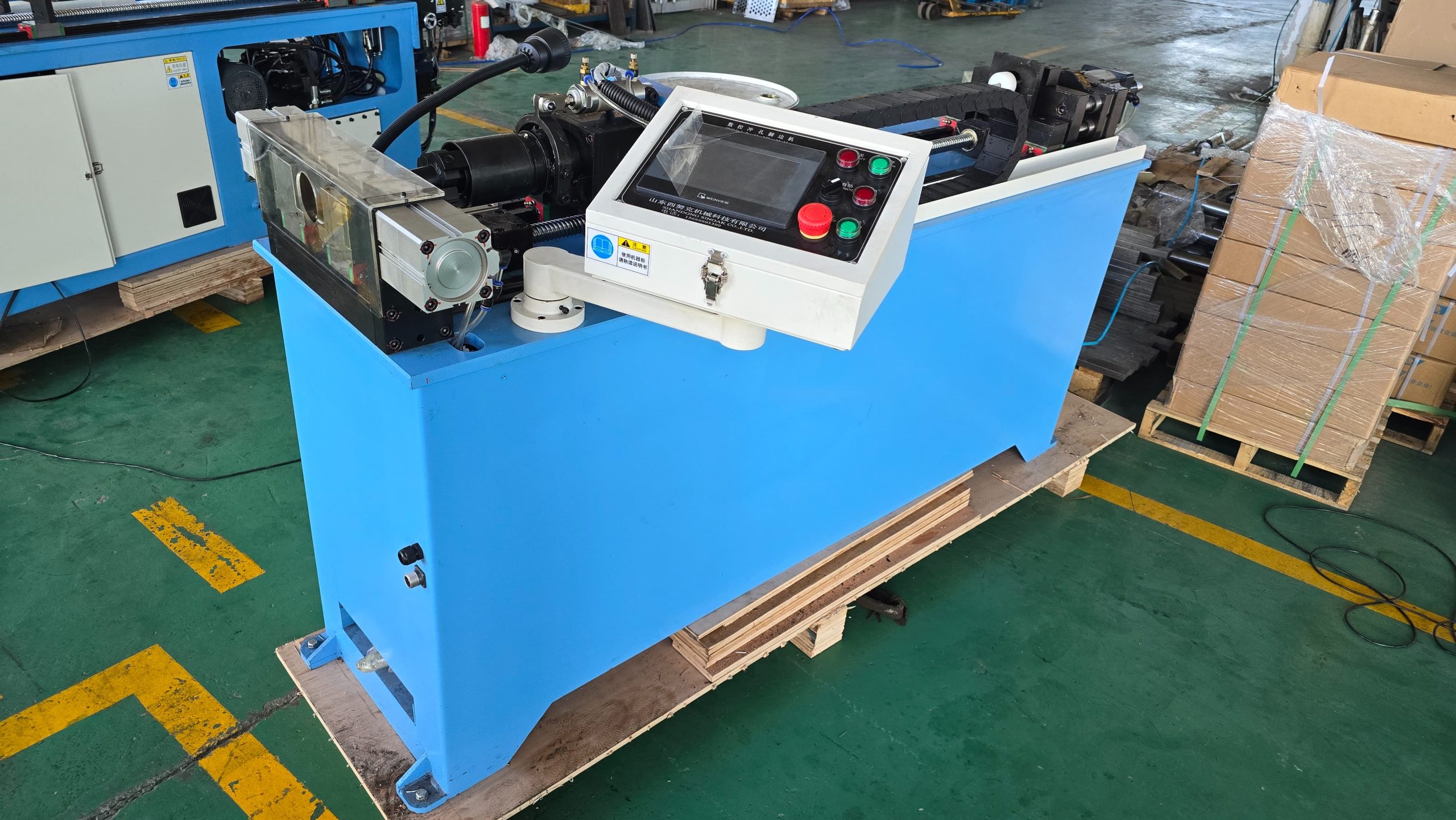
As a specialized supplier of complete HVAC&R coil manufacturing machinery—from hairpin benders and fin presses to vertical and horizontal tube expanders—we deliver engineered solutions tailored to your production demands.
Send your tube coil drawings and parameters to our engineering team today for a free plant layout proposal and customized quotation!