How to Handle Heat Exchanger Coils Without Damage
Steve
2026-09-22
How to Handle Heat Exchanger Coils Without Damage
Heat exchanger coil handling determines whether a conforming coil remains conforming between fin stamping, tube processing, expansion, brazing, testing, and packing. For safe manual lifting and material movement principles, consult CCOHS guidance on material handling. The production method still needs to be qualified for the coil size, weight, tube length, fixture, and local safety requirements.
A fin-and-tube coil is not a rigid block. Thin aluminum fins crush easily, long copper tubes can bend under their own weight, open tube ends can collect contamination, and similar models can be mixed in a busy work-in-process area. A reliable handling plan protects the part geometry, identifies the product, and keeps each transfer repeatable.
The goal is not simply to move coils faster. It is to move them without creating rework, hidden leak risk, blocked assembly, or unsafe lifting. That requires a defined support method at every process handoff rather than an improvised trolley or forklift route.
Why heat exchanger coil handling is a production process
Heat exchanger coil handling should be treated as a controlled production process because it affects product quality, labor time, and line availability. Damage may appear immediately as a crushed fin pack, but it can also emerge later as poor tube alignment, difficult return-bend assembly, or a leak caused by a scratched tube.
Handling objective | What must be protected | Typical loss when it fails |
Maintain coil geometry | Fin pack alignment, tube pitch, headers, and return-bend access | Insertion interference, expansion variation, and assembly rework |
Support long tubes | Straightness, surface condition, and tube-end shape | Bends, scratches, contamination, and cutting or brazing defects |
Keep the model identifiable | Part number, revision, circuit, material batch, and status | Model mix-up, incorrect recipe, and avoidable inspection |
Control work in process | Orientation, FIFO order, quantity, and buffer condition | Searching, excess WIP, missed defects, and delayed flow |
Protect people | Lift path, load stability, pinch points, and ergonomic reach | Dropped product, injury risk, and uncontrolled recovery |
Handling requirements change with the product family. A compact automotive coil may tolerate a small fixture, while a large commercial coil with long hairpins needs distributed support and a wider turning radius. Define the boundary product first: the largest, longest, heaviest, or most fragile coil that must travel on the route.

Map the coil route before selecting carts or lifting devices
Start with a route map from the first finished fin pack or tube bundle to the final packed coil. Show every pickup, set-down, inspection point, buffer, turn, door, and transfer between people or equipment. A cart that works at one station can fail at the next if the operator must lift over a guard or rotate a long coil in a narrow aisle.
- List each product family, including its maximum dimensions, weight, tube length, fin density, and permitted contact points.
- Mark where coil orientation must be maintained and where it may be safely changed.
- Identify any step where an operator currently supports one end by hand or removes a temporary support.
- Record the available floor space, aisle width, door openings, crane coverage, and fork-truck traffic.
- Define the maximum permitted WIP at each handoff and the visual method for FIFO and status identification.
- Trial the route with a boundary product before approving rack height, cart wheel type, lift points, or transfer time.
Choose a support method for the actual coil condition
The same coil may need a different fixture before and after tube expansion. Before expansion, open fins and inserted tubes are vulnerable to relative movement. After expansion, the core is more stable, but headers, return bends, and exposed tube ends may introduce new contact restrictions.
Coil condition | Suitable handling method | Design point to verify | Avoid |
Fin pack before tube insertion | Flat, clean, protected fin trays or guided transfer | Full fin-pack support and stack-height limit | Point loading on fin edges or unmarked stacks |
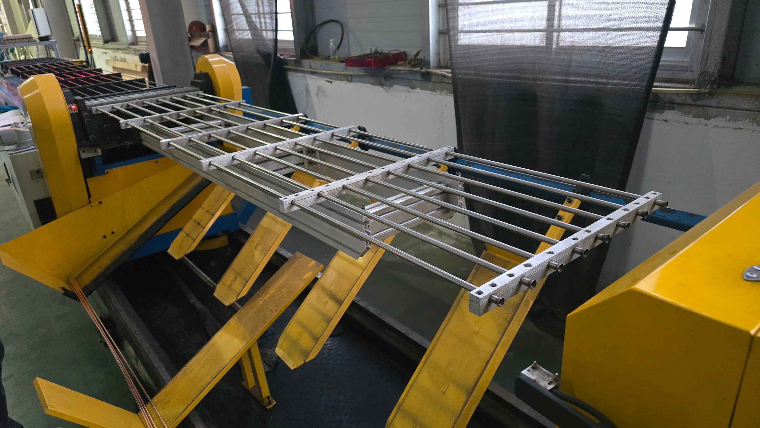
Long hairpins after bending | Multi-point tube rack, roller support, or guided collector | Support spacing, tube separation, and end protection | Allowing one tube end to overhang unsupported |
Laced core before expansion | Dedicated cradle with stable datum faces | Core orientation, fin-edge clearance, and transfer to expander | Clamping across fins or forcing the core through a narrow opening |
Expanded coil before brazing | Wheeled cradle, lifting frame, or assisted transfer | Header clearance, return-bend access, and controlled rotation | Fork contact with tube ends, fins, or temporary joints |
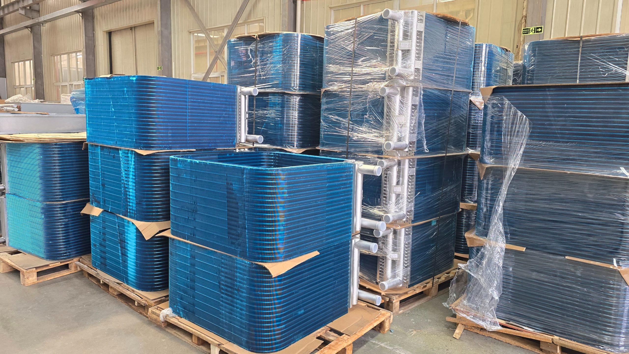
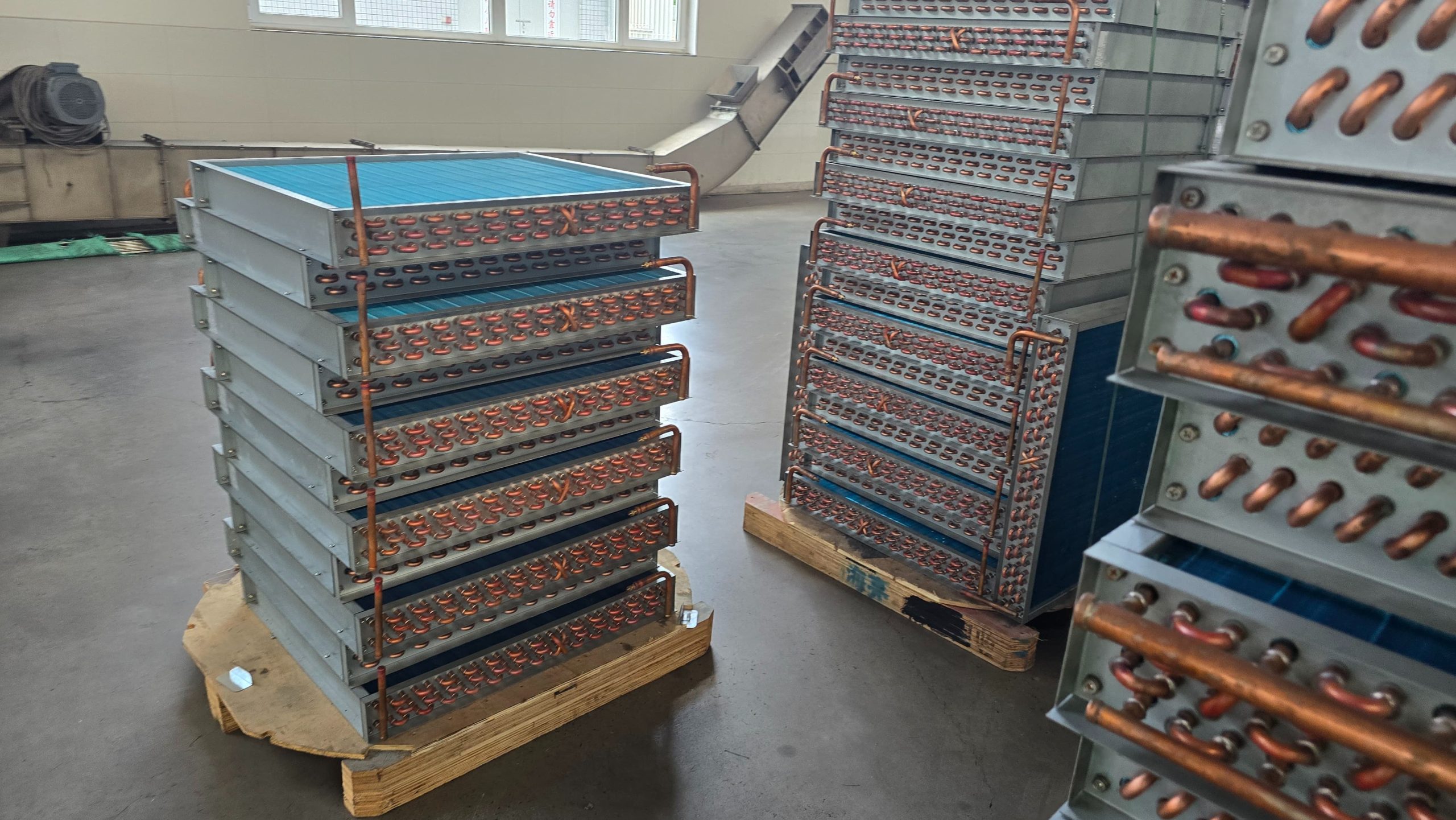
Tested coil awaiting packing | Identified FIFO rack with protected contact surfaces | Part traceability, dry condition, and maximum storage time | Mixing released and unreleased coils in one location |
Support points should contact a defined robust area, not a convenient fragile surface. Use smooth, clean contact surfaces and account for coil variation. A fixture that is correct for one core width can pinch or allow movement when another approved model enters the same route.
Heat exchanger coil handling controls for fins and tubes
Fins and tubes fail differently, so they need different controls. Fin damage is commonly caused by point contact, stacking pressure, or unprotected side contact. Tube damage often comes from unsupported length, dragging, clamp marks, or collision at turns and transfers.
- Keep contact surfaces away from active fin areas unless the support was designed specifically for that contact.
- Use enough support stations to prevent long tube deflection; set the spacing from the boundary tube length and wall condition.
- Separate sharp, dirty, or lubricated components from clean coil handling surfaces.
- Use positive location features to prevent a coil from rolling or sliding when a cart starts, stops, or turns.
- Protect open tube ends where contamination, deformation, or accidental contact may affect the next process.
- Define when gloves, sleeves, and cleaning steps are required to prevent surface contamination and injury.
Prevent mix-ups with visible status and controlled buffers
A handling system also carries information. Each coil or carrier should show enough information for the next operator to confirm part number, revision, route, quantity, process status, and any hold condition. The label must remain readable after cleaning, turning, and waiting in the buffer.
Control | Practical method | Reason |
Product identity | Barcode, traveler, carrier tag, or durable label linked to the coil | Prevents wrong model, wrong circuit, and wrong recipe |
Process status | Clear released, hold, rework, and awaiting-inspection states | Prevents untested or nonconforming coils from moving forward |
FIFO control | Defined rack lanes, maximum quantity, and first-in first-out rule | Limits aging, searching, and hidden queues |
Carrier ownership | One carrier type or adjustable fixture with controlled settings | Avoids unstable fit and undocumented contact points |
Damage feedback | Simple defect tag and route for crushed fin, bent tube, scratch, or drop event | Makes handling losses visible instead of treating them as random defects |

Common quality problems and how to correct them
Observed problem | Likely handling cause | Adjustment or optimization |
Crushed fin edges or local fin collapse | Hard point contact, high stack pressure, or cart side impact | Change the contact surface, add edge clearance, limit stacking, and review turns and braking |
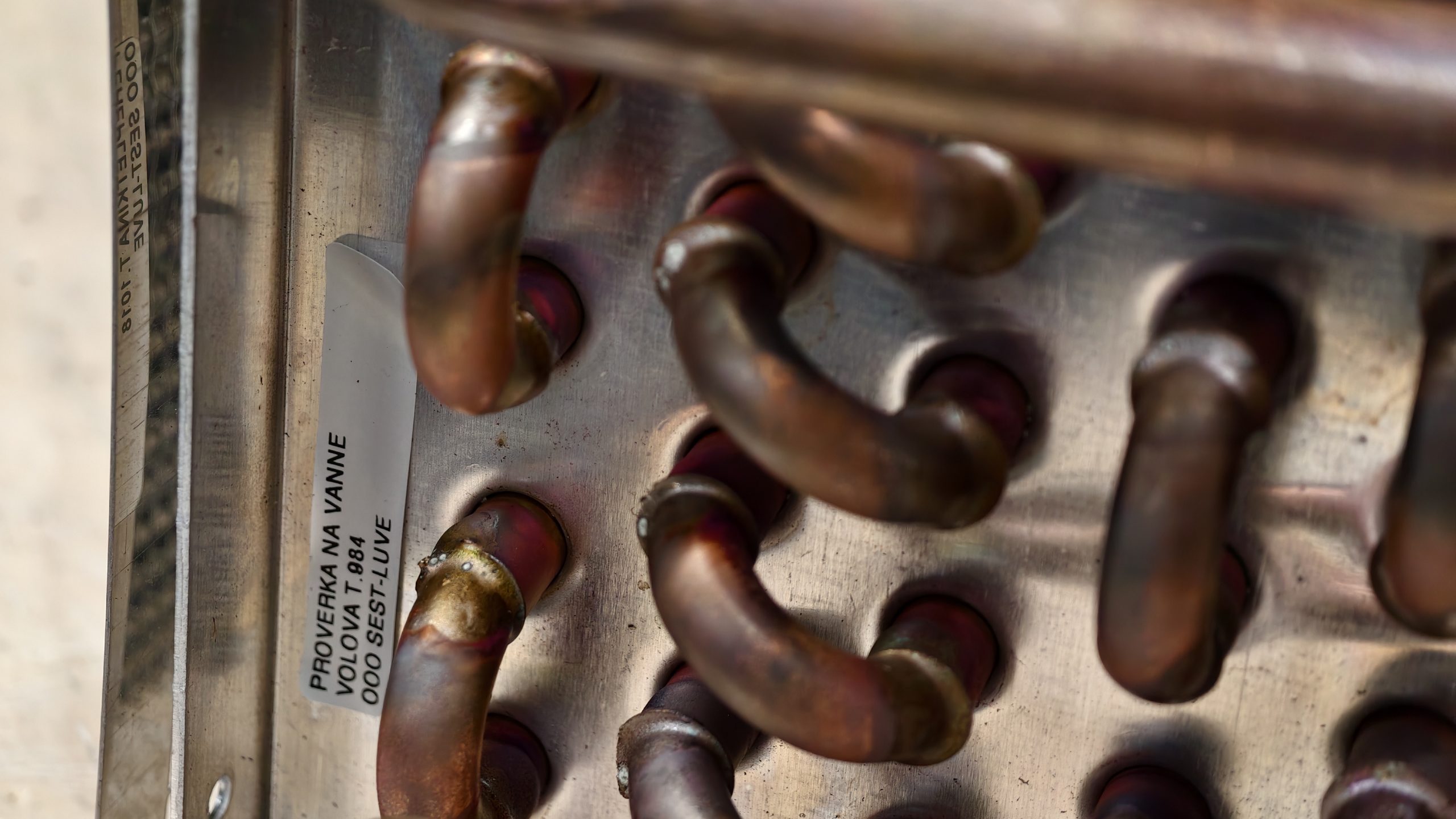
Bent or scratched copper tubes | Long unsupported overhang, dragging, clamp marks, or contact with metal frame | Increase support points, add non-marring guides, protect tube ends, and validate with boundary lengths |
Coil twists during lifting | Single-point lift, uneven support, or an undefined center of gravity | Use a spreader frame or multiple defined lift points; confirm balance before full lift |
Wrong coil reaches the next station | Similar products share an unsegregated buffer or labels are not readable | Create model-specific lanes, scan at handoff, and separate hold or rework locations |
Rework rises after a layout change | New vehicle route introduces vibration, sharp turns, or extra manual transfer | Measure travel, stops, and contact events; revise the route and handling method before adding inspection |
Do not solve repeated handling damage only by adding a final inspection. The effective correction is to identify the first damaging contact, clarify the permitted support method, and verify the result over repeated transfers. Inspection remains useful as a check, but it should not become the primary control.
Plan handling equipment with the production line
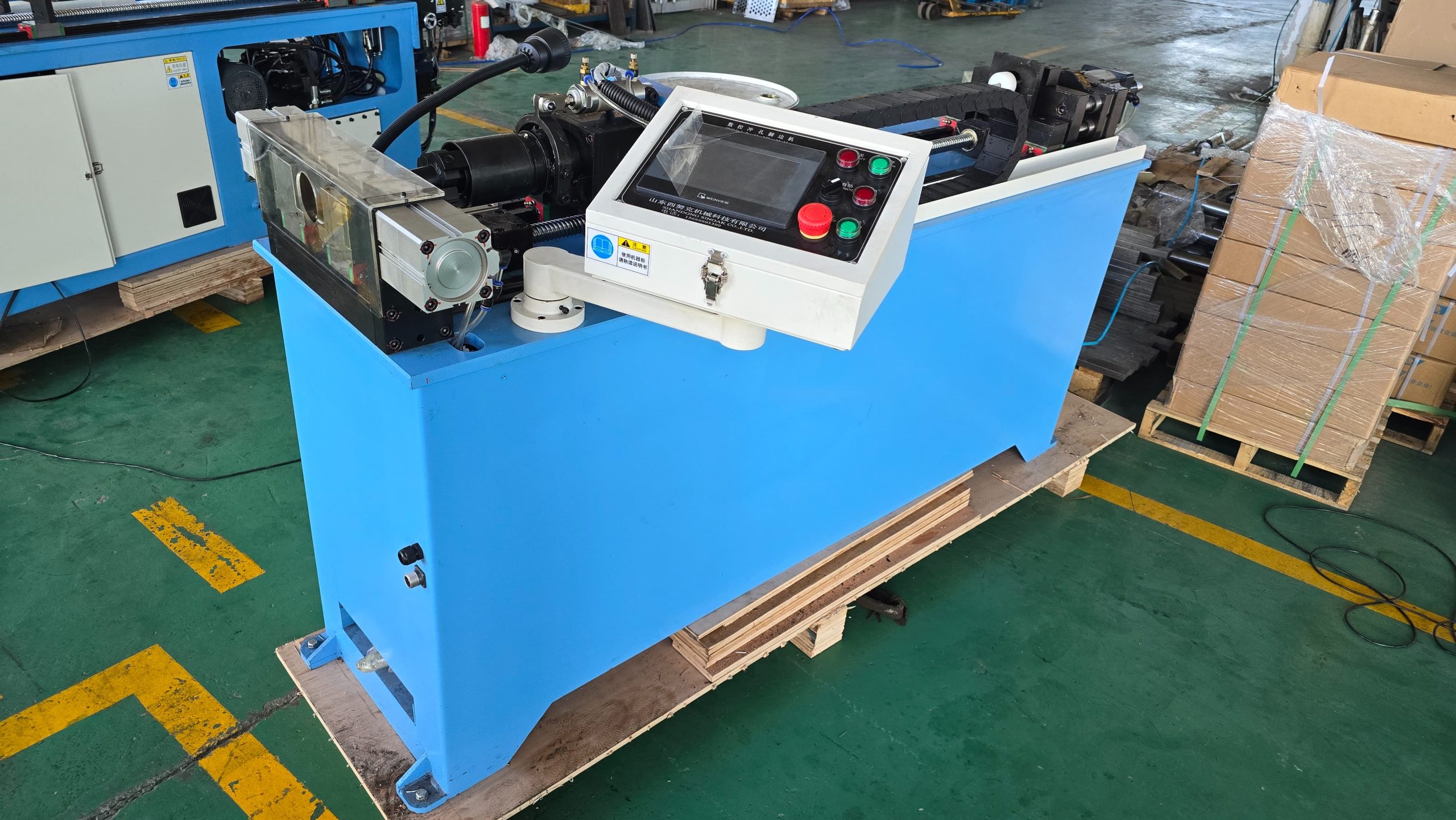
Handling equipment should be specified at the same time as fin presses, hairpin benders, expanders, brazing stations, and test equipment. The machine supplier needs to know loading direction, discharge height, cycle expectation, part orientation, and whether the product must be transferred manually, by cart, by hoist, or by automatic interface.
For a line concept that connects processing equipment with suitable material movement, review the available production equipment and technical support with SINOAK heat exchanger production equipment. SINOAK can assess representative coil drawings, production flow, and the available factory layout so machine interfaces and work-in-process handling are considered together.
For a growing factory, leave practical space for future carts, racks, lifting aids, and transfer interfaces. These items are often added after the main machines, but late additions can narrow aisles, block maintenance access, and create unnecessary manual lifts.
Acceptance checks for coil handling equipment
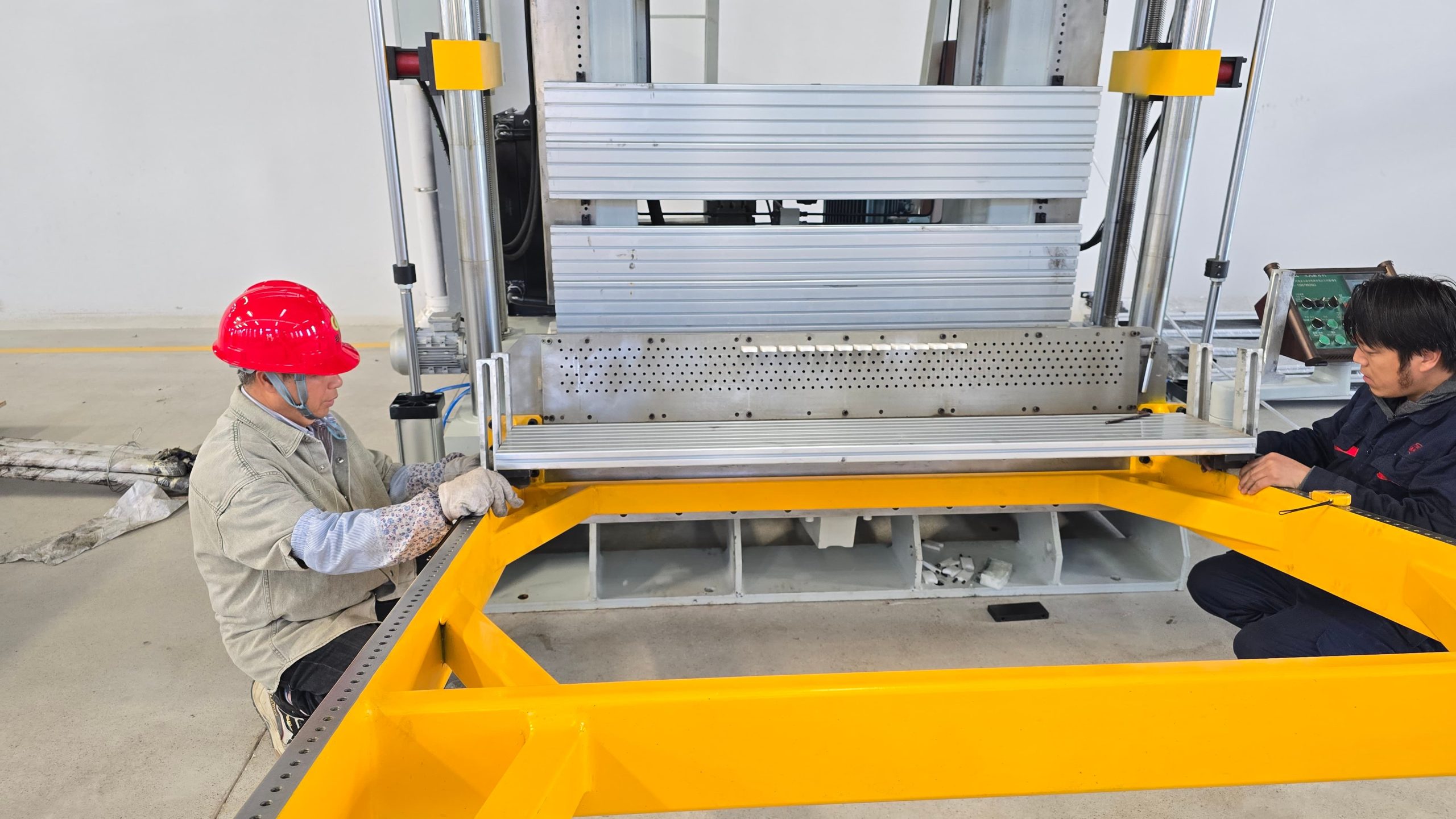
A cart, rack, cradle, or lifting fixture should be accepted with actual parts, not only an empty-frame demonstration. Include the shortest and longest tubes, largest core, heaviest coil, and a product that requires the most careful orientation.
- Confirm that all defined contact points are on approved robust surfaces and do not compress fins or deform tubes.
- Move the boundary product through acceleration, deceleration, turns, slopes, and handoff positions used in normal production.
- Check that the operator can load, unload, identify, and inspect the coil without reaching through a pinch point.
- Verify label visibility, FIFO position, and separation of released, hold, and rework product.
- Inspect the coil after repeated transfers for fin damage, tube scratches, change of orientation, or unstable support.
- Document cleaning, maintenance, adjustment, and abnormal-recovery responsibilities for the fixture or carrier.
FAQ
Can a forklift move heat exchanger coils directly?
Conclusion
Heat exchanger coil handling is part of the manufacturing method, not an afterthought. When the route, support points, status control, buffer limits, and lifting method are defined together, a factory protects fins and tubes while reducing search time, rework, and unsafe manual handling. The most useful system is the one proven with the real boundary products and repeated production transfers.
Recent News