Header Pipe Punching and Collar Extruding Machine Selection Guide for HVAC Manufacturers
Header Pipe Punching and Collar Extruding Machine Selection Guide for HVAC Manufacturers
Steve
2026-10-12
Header Pipe Punching and Collar Extruding Machine Selection Guide for HVAC Manufacturers
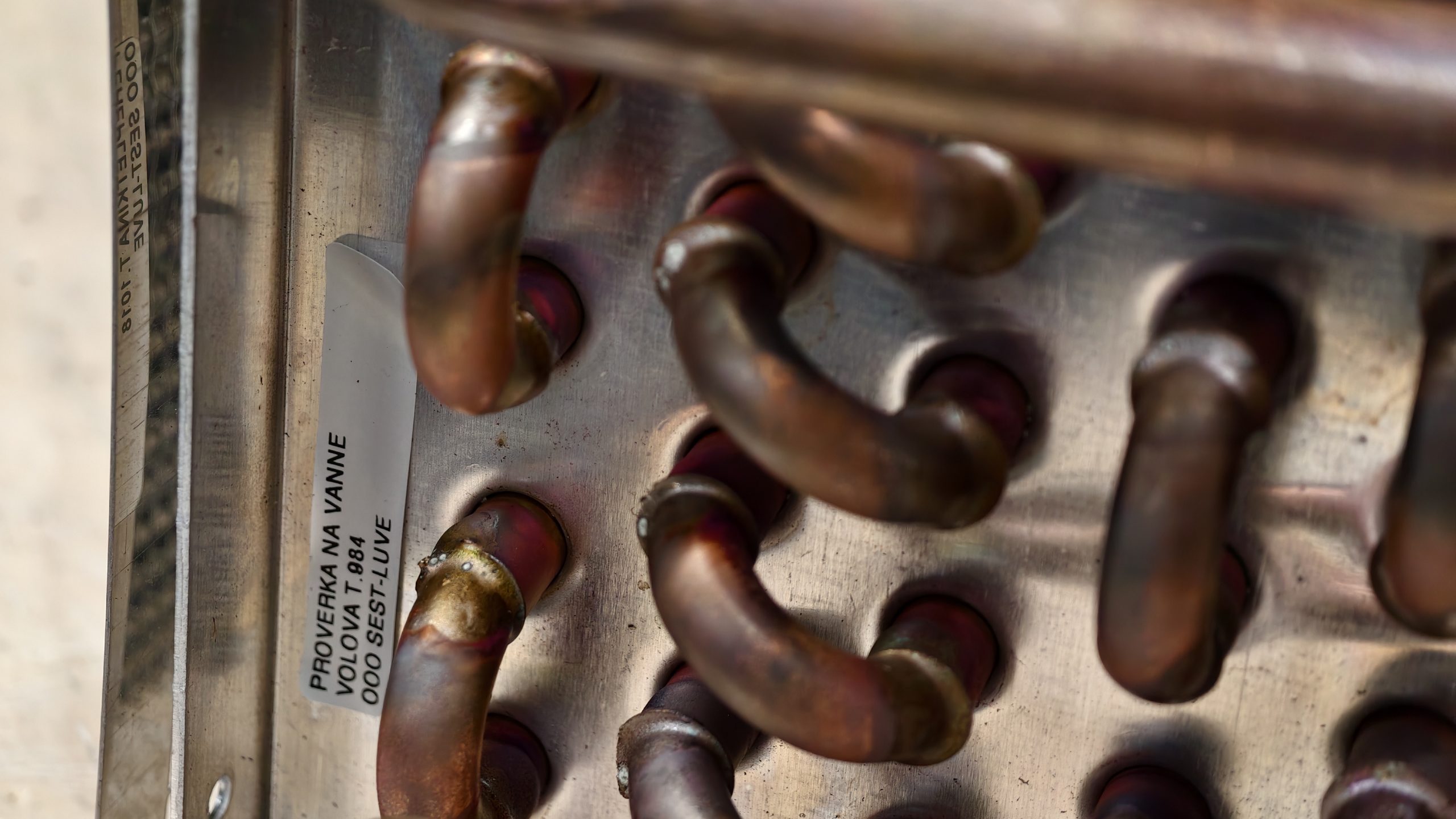
In modern HVAC&R condenser, evaporator, and air-cooler production, the header pipe (distribution manifold) serves as the central artery for refrigerant distribution. Joining multi-circuit capillary tubes or hairpin bends to the main suction/discharge header requires highly precise holes and extruded collars.
Historically, tube headers were manually drilled or punched—a slow, labor-intensive process that generated copper swarf, burrs, and inconsistent joint fits, leading to solder leakage during automatic brazing.
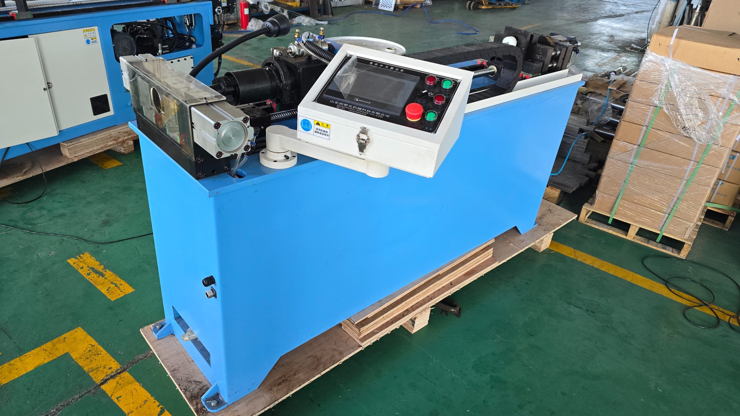
Today, CNC Automatic Header Pipe Punching and Collar Extruding Machines integrate multi-hole punching, spin-flanging (collaring), and indexable rotary feeding into a single automated cycle. This guide provides an engineering evaluation of punch vs. drill methodologies, collaring physics, machine drive architectures, and technical RFQ checklists.
1. Hole Processing Methodologies: Thermal Friction Drilling vs. Mechanical Collaring
When forming branch connections on copper, brass, or aluminum headers, two primary cold-forming technologies are used in modern production lines:
Mechanical Punching with Internal Pull-Collar (T-Extrusion)
Operating Principle: An internal mechanical mandrel enters the header tube, pierces a pilot hole, and pulls or extrudes an outward-facing lip (collar) in a single stroke.
Engineering Advantage: This method produces a completely clean, burr-free internal tube wall with zero metal chips entering the system. The outward-facing collar provides a large surface contact area for branch tube insertion, ensuring optimal capillary action during flame or induction brazing.
Operating Principle: A high-speed rotating tungsten carbide bit uses axial pressure and frictional heat (reaching between 600 circC and 800circ C) to locally plasticize the metal wall, extruding a bushing outward simultaneously.
Engineering Advantage: This approach is ideal for heavy-wall copper or steel headers where mechanical punching forces would otherwise distort or crush the main tube diameter.
2. Technical Comparison Matrix: Manual vs. CNC Servo Header Machines
Performance Parameter
Manual / Semi-Automatic Puncher
Fully Automatic CNC Servo Header Line
Pitch & Distance Accuracy
+-0.5mm (Mechanical pin positioning)
+- 0.05 mm (High-precision servo ball-screw)
Rotary Hole Angle Accuracy
Manual angular+
+-0.1 C (360-degree CNC servo indexing head)
Cycle Speed per Hole
8 – 15 seconds / hole
1.5 – 3.0 seconds / hole
Swarf / Chip Generation
High (Requires internal flushing/cleaning)
Zero (Drawn collar technique)
Changeover Time
45 – 60 minutes
< 10 minutes (HMI recipe selection)
Brazing Leak Rate
2% – 5% (Due to uneven gap fit)
< 0.1% (Uniform capillary gap)
3. Key Selection Factors for Heat Exchanger Production Lines
To specify the correct machine model for your factory floor, evaluate the following structural parameters:
Commercial AC & Evaporators: Standard headers range from OD 12.7 mm to OD 38.1mm with wall thicknesses from 0.8 mm to 1.5 m
(2) Number of Branch Hole Rows & Angular Orientation
Multi-circuit heat exchangers often require branch connections along different angles around the tube circumference.
Choose a machine equipped with a servo-driven rotary C-axis (indexing chuck) that rotates the header pipe automatically between punch strokes without manual intervention.
(3) Collar Height and Capillary Fit Tolerance
To ensure proper silver alloy capillary flow during automatic brazing, the extruded collar height should ideally equal 1.5 to 2 times the header wall thickness.
Verify that the machine’s tooling features adjustable expansion arbors to accommodate your exact branch pipe outer diameters (e.g., 5 mm, 7mm, 9.52 mm).
Automating your header pipe processing eliminates the primary bottleneck in coil assembly and drastically reduces manual brazing defect rates.
To help our technical engineering team design a custom CNC header punching machine and prepare an itemized quote, please provide the following parameters with your inquiry:
RFQ Technical Information Checklist:
Header Pipe Specifications:
Tube Material (Copper / Aluminum / Brass / Stainless Steel)
Header Outer Diameter (OD) range (e.g., +- 15.88 mm to +- 66.7 mm)
Header Wall Thickness range (e.g., 1.0 mm to 2.5 mm)
Minimum and Maximum Header Pipe Length (L) (e.g., 300 mm to 2,500 mm)
Branch Hole & Collar Geometry:
Branch tube ODs to be inserted (e.g., 5 mm, 7mm, 9.52mm)
Expected header output per shift (e.g., headers per 8-hour shift)
Preferred machine control system (Full CNC Servo / Pneumatic-Hydraulic)
Integration preference (Standalone machine vs. Automated conveyor feeding)
Plant Facilities & Utilities:
Shop floor footprint limits
Power supply standard
Compressed air pressure rating and hydraulic cooling environment
As a specialized manufacturer of complete HVAC&R tube processing machinery—including automatic hairpin benders, fin press lines, tube expanders, and CNC header pipe punchers—we engineer equipment tailored to your exact production tolerances.
Send your header tube shop drawings and production targets to our engineering team today for a free plant layout drawing, process evaluation, and quotation!