How to Select the Right High-Speed Fin Press Line for Your Plant
How to Select the Right High-Speed Fin Press Line for Your Plant
Steve
2026-10-14
How to Select the Right High-Speed Fin Press Line for Your Plant
In HVAC&R heat exchanger manufacturing, the high-speed fin press line is the starting point of the entire coil production ecosystem. Responsible for stamping thin aluminum or copper foil into structured heat transfer fins, the performance of your fin press line directly dictates your daily plant capacity, fin collar precision, and downstream assembly efficiency.
Selecting the right fin press line involves much more than simply choosing a machine tonnage. It requires evaluating dynamic balancing, stroke control, lubrication systems, fin die compatibility, and automated stacking mechanisms.
This guide provides a detailed technical roadmap to help coil manufacturers evaluate, specify, and select the ideal high-speed fin press line for their production requirements.
1. Core Component Modules of a Fin Press Line
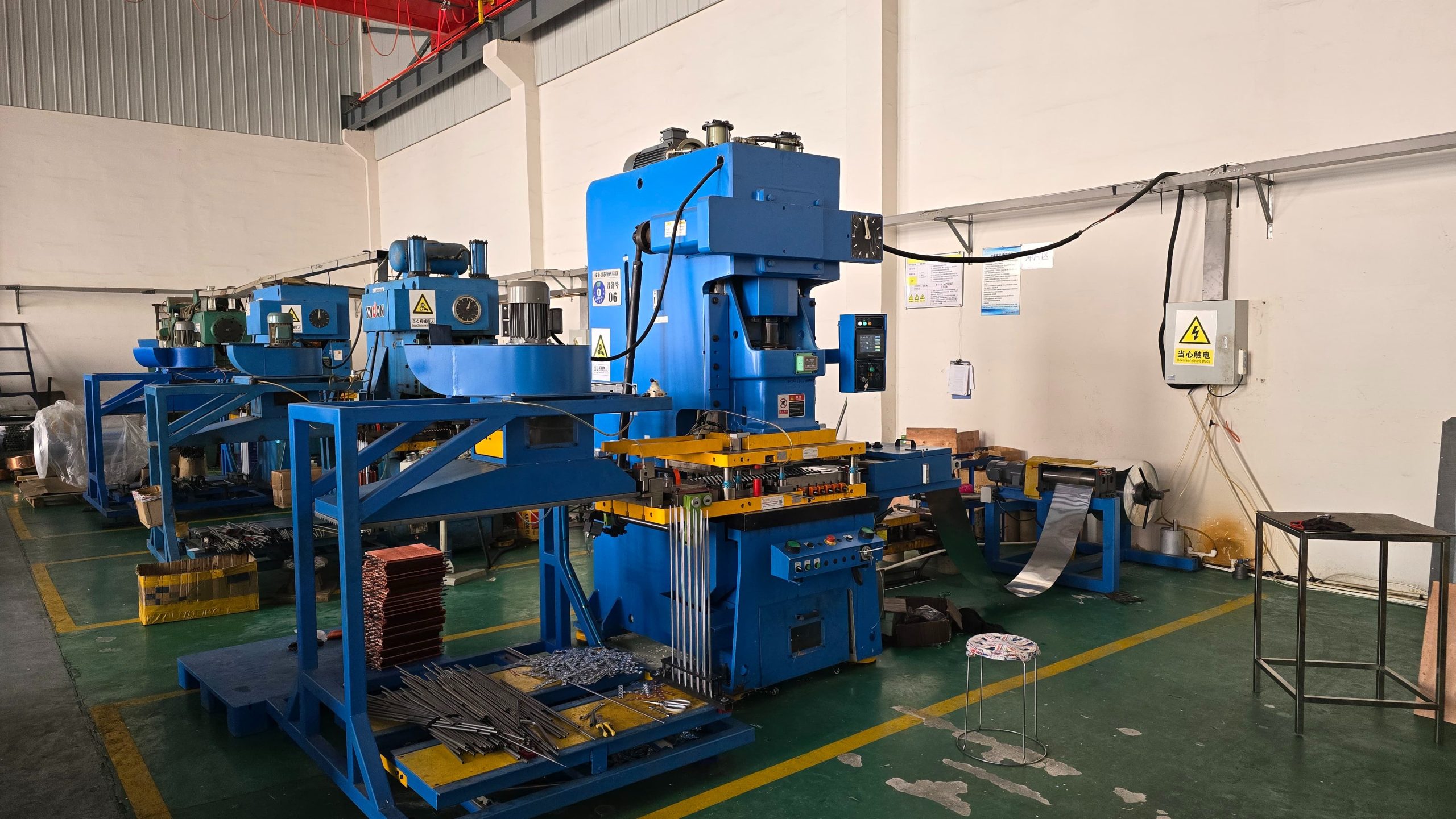
A modern automated fin press line operates as an integrated system consisting of four synchronized machinery modules:
Uncoiler and Tension Control System: Unreels raw aluminum foil (typically 0.11mm to 0.20 mm thick) from heavy level-wound coils. It features pneumatic tension brakes and loop control sensors to ensure smooth, jerk-free foil feeding without stretching or tearing the material edges.
Oil Tank & Micro-Lubrication Unit: Applies a precise, uniform film of vanishing oil or food-grade lubricant across both sides of the foil. Proper lubrication is essential to extend progressive fin die life and prevent aluminum galling during high-draw collar forming.
High-Speed Precision Stamping Press: The central power unit driving the progressive fin die. Equipped with a high-rigidity frame, precision guided slide rails, and variable frequency speed drives, it performs punching, drawing, louvering, and cut-off operations at high strokes per minute (SPM).
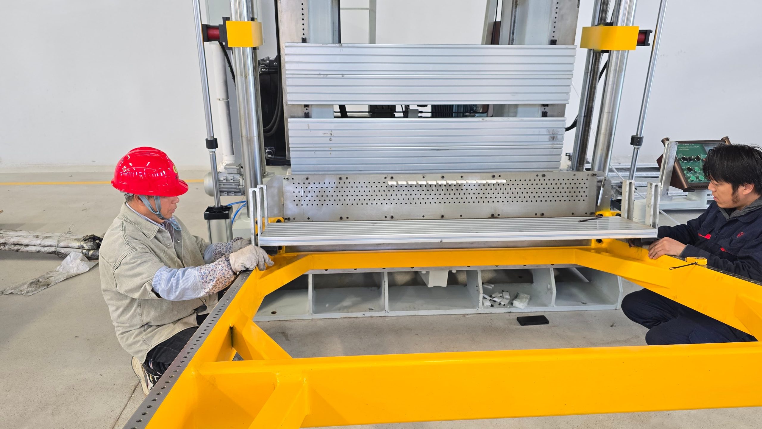
Vacuum / Air-Blow Fin Stacking System: Collects and counts cut-to-length fin strips automatically. Utilizing suction beds or guided air-jets, it stacks fins neatly onto transport carts without damaging delicate collar edges or flattening wave profiles.
2. Technical Comparison: C-Frame vs. H-Frame Fin Presses
Choosing the right press frame structure is the most critical decision when configuring a fin press line:
Performance Metric
C-Frame Fin Press Line
H-Frame Fin Press Line
Frame Architecture
Single-column, open-front “C” structure
Closed-loop, symmetrical 2-column or 4-column structure
Structural Rigidity
Moderate (Slight angular deflection under peak loads)
Extremely High (Zero angular deflection across the bed)
Tonnage Range
30 tons to 45 tons
60 tons to 100+ tons
Die Accessibility
High (3-side open access for quick die changes)
Restricted side access due to heavy corner pillars
Max Fin Rows & Speed
Ideal for 1 to 4 row dies; 150–250 SPM
Ideal for multi-row (6–12+ row) dies; 250–300+SPM
Best Suited For
High-mix, medium-volume commercial lines
Continuous, high-volume mass production lines
3. Key Technical Selection Criteria
To ensure your investment delivers maximum ROI, evaluate these core engineering factors before placing an equipment order:
Stroke Speed (SPM) and Dynamic Balancing
High-speed stamping generates substantial dynamic vibrations. Look for press models equipped with dynamic balancing counterweights that offset slide movement forces. A well-balanced press runs smoothly at 250–300 strokes per minute without transmitting destructive vibrations into the foundation or fin die punches.
Hydraulic Overload Protection and Slide Adjustment
During setup or feeding jams, double-thickness foil can enter the die cavity. An integrated hydraulic overload protection system instantly dumps hydraulic pressure, stopping the slide in milliseconds to prevent catastrophic fin die damage. Additionally, motorized slide adjustment with digital readout simplifies die shut-height calibration.
Vacuum Stacking vs. Mechanical Drop Stacking
Vacuum Stacking: Uses negative pressure belts to hold fins from above, releasing them gently onto the stacking tray. This is mandatory for thin-wall, high-louver fins where mechanical dropping causes bent collars or overlapping jams.
Air-Blow / Mechanical Stacking: Uses directional air nozzles to assist falling fins. Economical and effective for thicker foil or standard commercial fins with wider collar spacing.
Specifying the correct high-speed fin press line requires providing your machinery vendor with complete foil, die, and capacity requirements.
To help our technical engineering team design a custom fin press line and prepare an itemized quote, please review and share the following specifications with your inquiry:
RFQ Technical Information Checklist:
Foil & Material Specifications:
Foil material type (Bare Aluminum / Hydrophilic / Epoxy Coated / Copper)
Foil thickness range (e.g., 0.095mm to 0.20 mm)
Max aluminum coil outer diameter (OD), inner core diameter, and coil weight
Fin Die & Geometric Parameters:
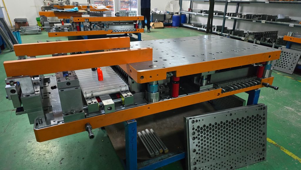
Fin die dimensions (Length $\times$ Width $\times$ Shut Height)
Number of tube rows and target collar height range
Maximum required fin strip length (L)
Capacity & Speed Goals:
Target operating speed (Strokes Per Minute – SPM)
Expected daily fin output per 8-hour shift
Preference for press frame type (C-Frame vs. H-Frame)
Plant Utilities & Layout:
Available factory footprint (L *W *H clearance)
Power supply standards 380V / 50Hz/ 3-Phase)
Compressed air pressure and air displacement capacity
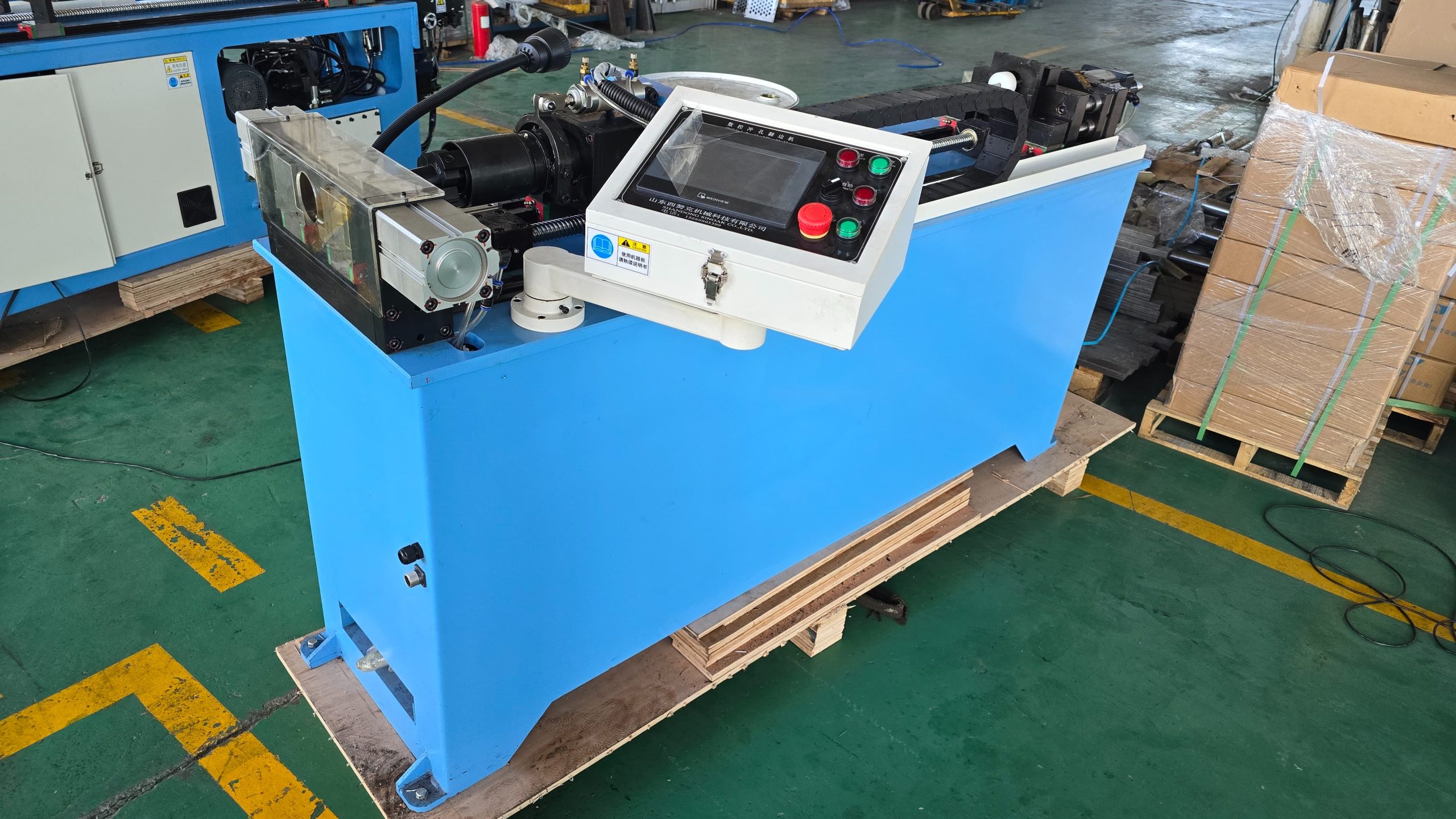
As a specialized engineering manufacturer of complete HVAC&R machinery—including high-speed fin press lines, custom fin dies, automatic hairpin benders, and tube expanders—SINOAK delivers complete production solutions tailored to your technical requirements.
Contact our engineering support team today with your fin drawings to receive a free plant layout consultation and customized machinery proposal!