How Heat Exchangers Are Manufactured
Steve
2026-09-20

How Heat Exchangers Are Manufactured
heat exchanger manufacturing process planning starts with the finished coil specification, then works backward through fin forming, copper tube preparation, tube insertion, expansion, testing and handling. A stable line does not come from one fast machine. It comes from matched process windows, controlled material flow and quality checks that prevent defects from moving to the next operation.
For the thermal and refrigeration context behind a finned coil, the ASHRAE Handbook is a useful technical reference. Manufacturing settings still need to be validated with the actual tube, fin, refrigerant circuit and duty conditions of each product.
The same basic sequence can serve fan coils, unit coolers, condensers, evaporators and industrial equipment. However, tube diameters, fin geometry, coil size, circuit layout, production volume and changeover frequency can change the right equipment configuration completely.
Heat Exchanger Manufacturing Process From Coil to Test
|
Production step |
Main purpose |
Typical equipment |
Critical control |
|
Fin forming |
Produce fins with the required pitch, collar, louver and surface condition. |
Fin press line, fin die, decoiler, feeder and collection system. |
Material tracking, feed accuracy, die condition, burr control and fin collection. |
|
Tube preparation |
Straighten, cut or form copper tube into the required hairpin or straight-tube geometry. |
Tube straightening and cutting machine, hairpin bender and tube supports. |
Tube length, end condition, bend radius, ovality, scratches and batch identification. |
|
Fin pack assembly |
Stack fins, side plates and support elements in the correct order before tubes are inserted. |
Fin stacking, assembly fixtures and controlled buffers. |
Fin orientation, fin pitch, product separation and protection from bending or crushing. |
|
Tube insertion |
Place tubes through the aligned fin collars without damaging the fin pack. |
Tube insertion machine, guides, supports and loading fixtures. |
Tube-to-fin alignment, insertion force, tube-end position and prevention of mixed circuits. |
|
Tube expansion |
Mechanically connect tubes and fin collars to create a repeatable contact interface. |
Vertical or horizontal tube expander, mandrels and coil fixtures. |
Expansion window, tube projection, fin damage, coil support and dimensional stability. |
|
Testing and finishing |
Confirm integrity, prepare connections and route the qualified coil to the next operation. |
Leak test equipment, pressure test station, handling and marking system. |
Test method, traceability, rejection containment and protection during transfer. |
This sequence should be treated as a connected system. A length problem created in tube preparation can become a tube-insertion issue. A scratch caused during coil handling can appear later as a leak-test reject. Process planning must therefore define both each machine and the transfer conditions between machines.

Fin Forming Sets the Geometry of the Coil
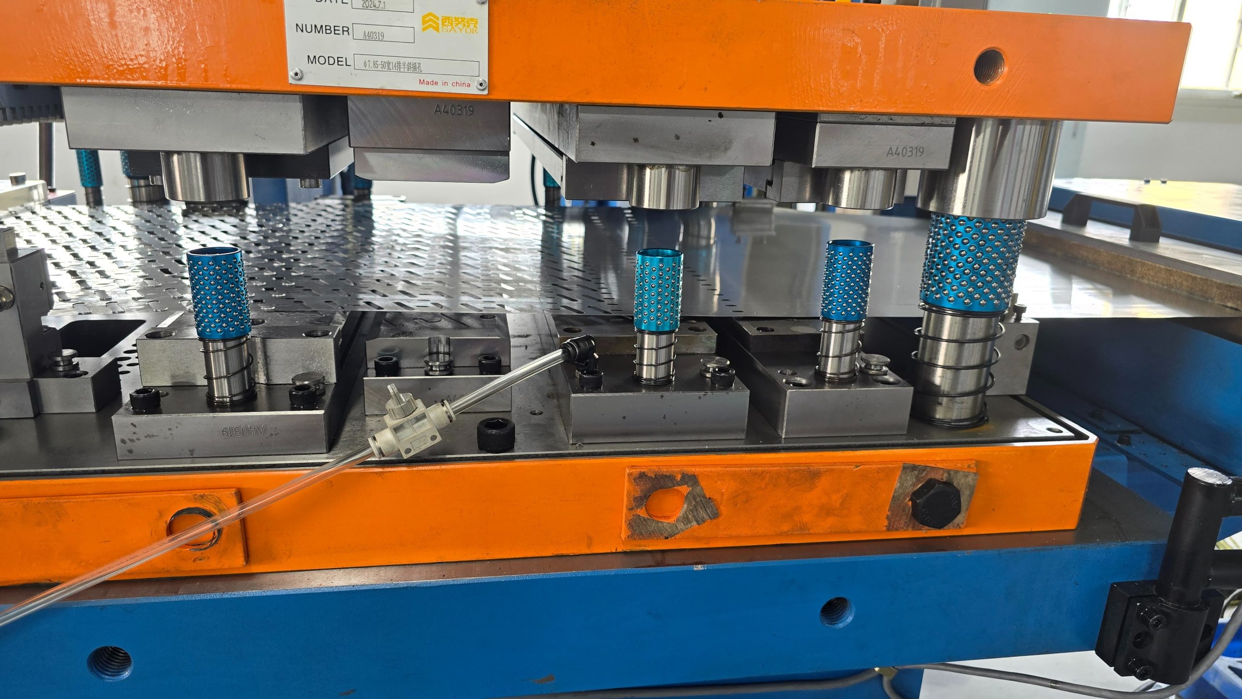
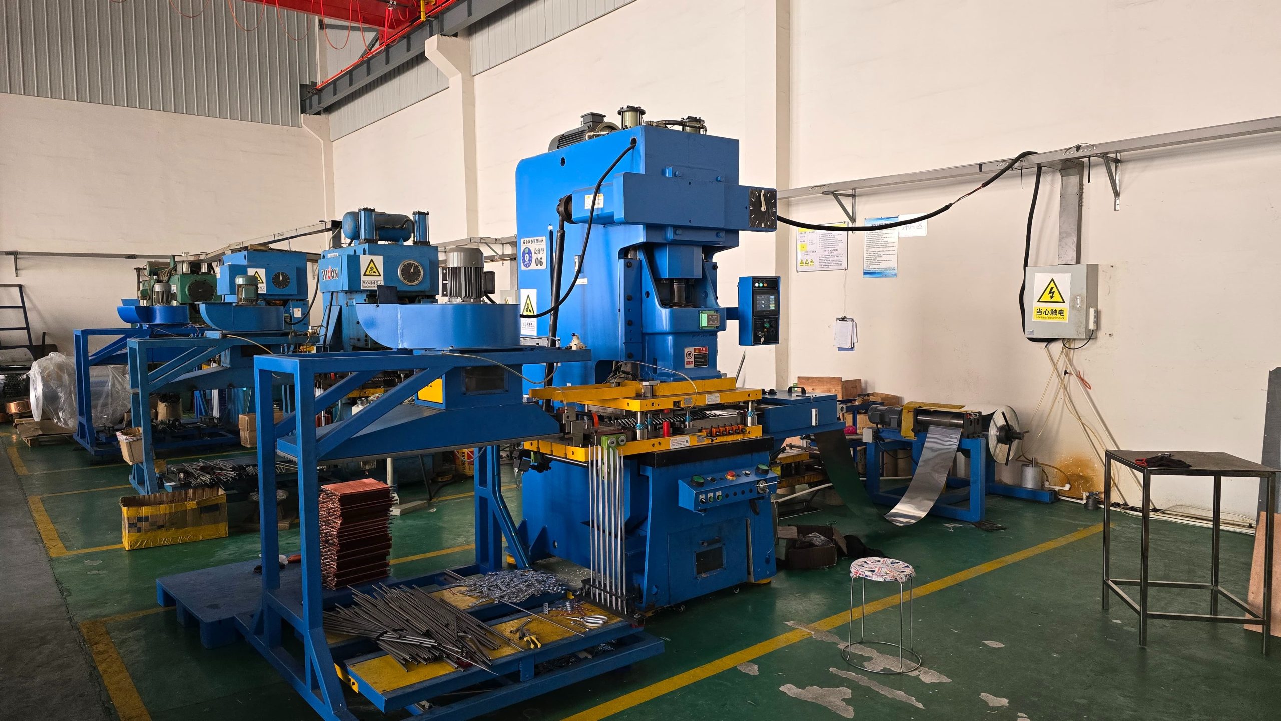
Fin forming is where the air-side structure of the heat exchanger is established. The fin press, die, feeder and material condition must work together to produce a consistent fin pitch, collar profile, louver pattern and burr level. These features influence not only coil performance but also the ability to insert and expand tubes reliably.
- Confirm aluminium alloy, temper, thickness, coating, coil width and permitted batch variation before defining the die and feeder window.
- Evaluate qualified fins delivered to the next operation, not only press strokes per minute.
- Keep scrap flow, fin collection and product identification under control so mixed fins do not reach assembly.
- Plan die changes, lubrication, inspection and safe maintenance access as part of the production cycle.
Copper Tube Preparation and Hairpin Bending
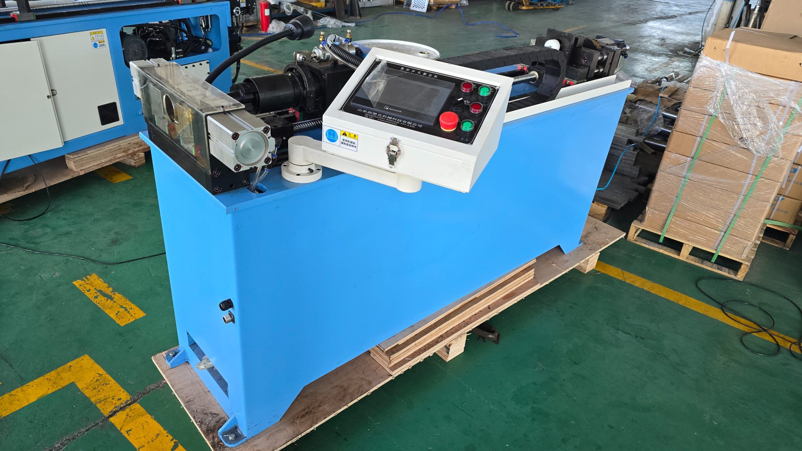
Copper tube preparation determines the reference dimensions entering the coil. The factory may process material from coil directly to a hairpin, or straighten and cut tube before a separate bending operation. The best route depends on the stability of the product family, the level of material variation, the need for flexible changeovers and the cost of repeated manual handling.
|
Tube route |
Best fit |
Points to validate before selection |
|
Coil to hairpin in one flow |
Stable products with repeatable tube sizes, lengths and bend forms. |
Pay-off, straightening, measuring, cutting, bending, unloading, fault recovery and material traceability. |
|
Straighten and cut before bending |
Mixed products, trials or production plans needing flexible separation of tube preparation and bending. |
Straight-tube storage, long-tube support, loading errors, transfer damage, changeover and buffer control. |
Tube preparation should not be judged by cycle time alone. Long tubes need controlled support, clear location references and protected contact surfaces. Otherwise, light bends, scratches or inconsistent tube ends can be created before the tube reaches the fin pack.
Fin Pack Assembly and Tube Insertion
At assembly, the process changes from individual components to a coil core. Fins need to be stacked in the correct direction and pitch, side plates need to be aligned, and tubes need to enter collars without forcing the fin pack out of position. A tube insertion machine can improve consistency, but only when the incoming fin pack and tube condition are already stable.
- Set product-specific fixtures, guides and supports from the actual fin pack dimensions and tube pattern.
- Define where first-piece confirmation checks fin orientation, tube route, tube-end projection and circuit identity.
- Separate qualified fin packs, work-in-progress and rework material by product and batch.
- Balance insertion output with expansion and downstream handling so coils do not wait in an unprotected buffer.
Tube Expansion Creates the Tube Fin Contact
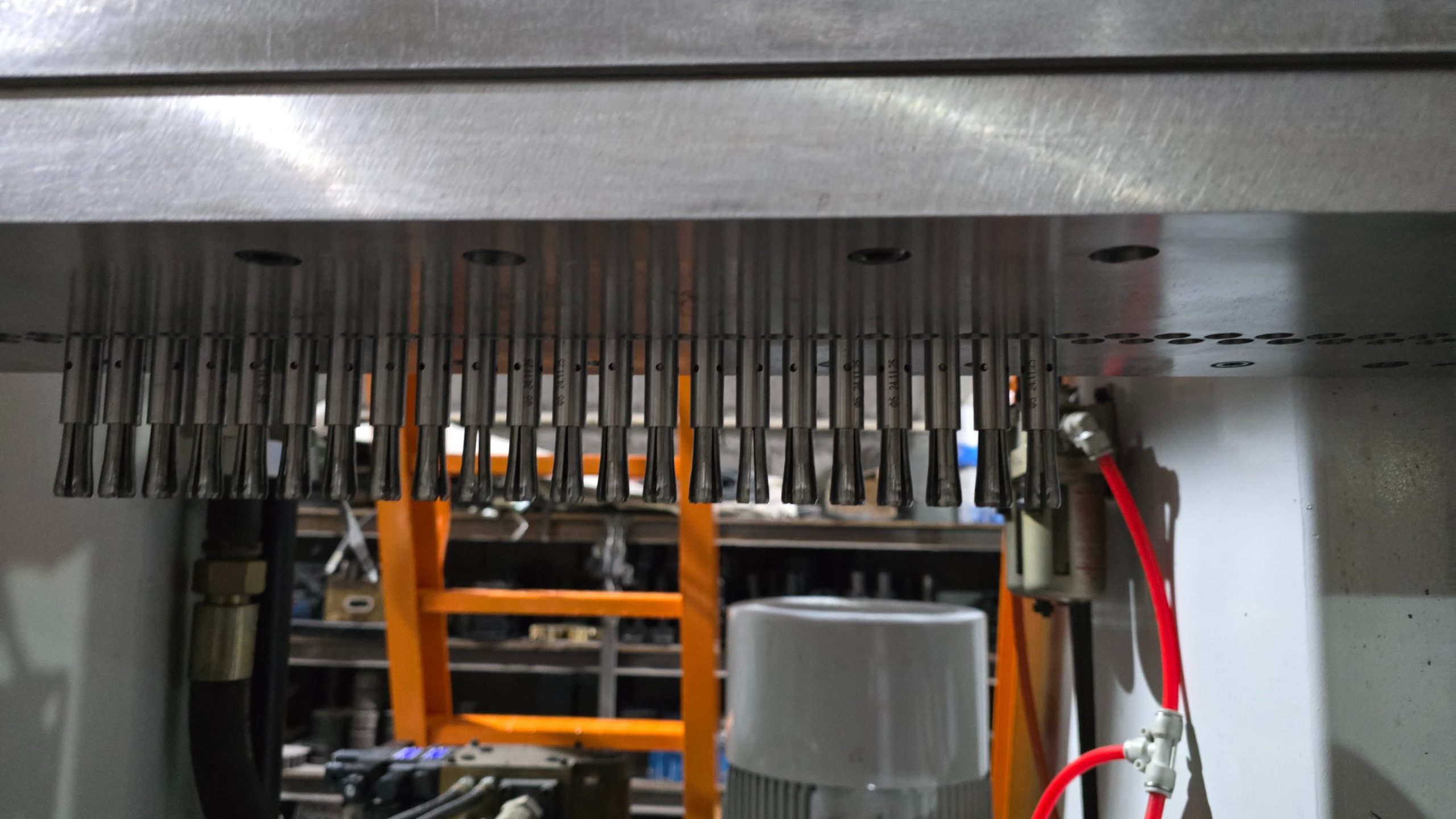
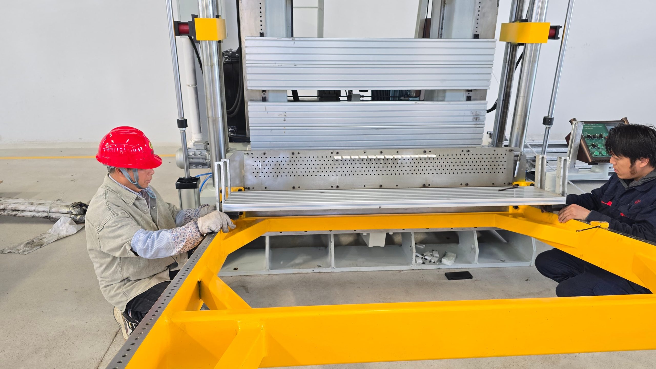
Tube expansion is the operation that develops the mechanical connection between tube and fin collar. The process must be matched to tube diameter, wall thickness, fin-hole condition, coil structure and required tube projection. Vertical and horizontal expanders can both be effective when the coil is supported, located and unloaded in a controlled way.
The goal is not to use the highest possible expansion force. The goal is to establish a validated parameter window that gives uniform contact without creating excessive tube deformation, collar damage, coil twist or a difficult downstream operation.

Testing and Handling Protect Qualified Coils
After expansion, the coil still needs to reach test and final assembly without damage or confusion. Leak testing, pressure testing, connection preparation and identification should be arranged so a non-conforming coil is contained immediately and a qualified coil retains its product and batch identity.
|
Control area |
Practical requirement |
Risk if missed |
|
Test method |
Define the applicable test medium, pressure, duration, acceptance limit and retest procedure for the product. |
Inconsistent rejects, missed leaks or test results that cannot be compared across shifts. |
|
Coil handling |
Use supported transfer paths, protected contact surfaces and clear container rules for each coil family. |
Fin scratches, tube-end damage, deformation and untraceable mixed work-in-progress. |
|
Rejection control |
Mark, isolate and record non-conforming coils before they return to repair or rework. |
Defects re-enter the line, repeat test failures and unreliable quality data. |
|
Downstream interface |
Match release quantity and direction to connection, brazing, casing or final assembly operations. |
Uncontrolled buffers, waiting time and avoidable handling damage. |
Common Manufacturing Problems and Improvements
|
Observed issue |
Likely causes |
Improvement direction |
|
Fin pitch, collar or burr variation |
Die wear, material variation, unstable feed, unsuitable lubrication or incomplete first-piece verification. |
Confirm die condition and material data; validate feed and lubrication with continuous samples before raising output. |
|
Tube scratches or inconsistent developed length |
Poor guides, worn contact points, insufficient long-tube support, feed slip or uncontrolled manual transfer. |
Inspect every contact surface; define tube support and verify length from representative material batches. |
|
Tube insertion jams or fin damage |
Fin pack is not aligned, tube ends are unsuitable, guides are incorrect or product variants are mixed. |
Stabilize incoming fins and tubes first; use product-specific guides, first-piece checks and batch separation. |
|
Uneven expansion or distorted coil |
Inconsistent coil location, unsuitable mandrel or recipe, uneven support, fin-hole variation or wrong action sequence. |
Establish product-specific expansion recipes and full-coil measurements; improve supports and location before increasing force. |
|
High output but low qualified delivery |
Equipment is optimized separately while changeover, inspection, buffers and downstream takt time are ignored. |
Measure qualified coils delivered to the next operation, including stops, rework, transfer and recovery time. |
When quality becomes unstable, do not solve the issue by changing one machine setting in isolation. Review material condition, tooling, product location, transfer points and the inspection method together. This creates a repeatable baseline before capacity or automation is increased.
Planning Heat Exchanger Production Equipment
Heat exchanger production equipment should be planned from the required product range and qualified output. A line can begin with independent machines and controlled buffers, or it can combine operations into a more continuous system. The choice should reflect product stability, expected changeover, available floor space, labor model, maintenance capability and the interfaces needed for future expansion.
- List every coil family, including tube size, fin geometry, coil dimensions, circuit layout, monthly demand and expected product changes.
- Map the route of material from fin coil and copper tube arrival through finished-coil release, including every manual transfer and buffer.
- Define quality gates for fins, prepared tubes, inserted fin packs, expanded coils and tested coils.
- Measure actual cycle time, changeover, waiting, inspection, rework and recovery time at each step.
- Confirm utilities, safety zones, maintenance access, long-workpiece support and data or traceability needs before finalizing the layout.
Reviewing a Line With SINOAK
SINOAK can review coil drawings, fin and tube specifications, target output, product mix and the factory layout to define a practical sequence of production equipment. The review can identify whether the main opportunity is a stand-alone process improvement, a better material route, a change in handling, or a more integrated line configuration.
For an initial review, provide representative coil drawings, production targets and factory conditions to SINOAK heat exchanger production equipment and technical support. The most useful proposal is one that makes the production boundary, quality checks and next-stage interface clear before equipment is specified.
FAQ
Manufacturing Process Questions
What is the first step in heat exchanger manufacturing
Which machine has the greatest effect on coil quality
Conclusion
A reliable heat exchanger manufacturing process is a connected chain of forming, tube preparation, assembly, expansion, test and protected handling. When each operation is selected and validated in relation to the next one, manufacturers can improve qualified output without simply adding speed, labor or work-in-progress.
Последние новости