HVAC Coil Manufacturing Differences by Product and Process

HVAC Coil Manufacturing Differences by Product and Process

HVAC coil manufacturing starts with the required thermal duty, refrigerant or fluid, air-side conditions, operating pressure, dimensions, and service environment. Designers and manufacturers can consult the ASHRAE Handbook technical resources. The production route must then be qualified for the exact drawing, material, joining method, and test requirement.

A fin-and-tube coil for a room air conditioner, refrigerated display case, condensing unit, dry cooler, or air-handling unit may look similar from a distance, but the manufacturing workload can be very different. Tube diameter, fin material, core size, circuiting, operating pressure, connection design, and acceptable leakage risk all affect equipment configuration and process control.

The practical question is not whether one line can make every HVAC coil. It is which product families can share tooling, feeding, fixtures, expansion settings, joining stations, test methods, and handling routes without compromising stability or creating excessive changeover.

HVAC coil manufacturing begins with product families

Product family

Common manufacturing features

Main production implication

Comfort air-conditioner coil

High volume, compact core, repeatable tube count, narrow cost target

Favors stable tooling, fast feeding, controlled handling, and short changeover

Commercial refrigeration coil

Wide model range, corrosion exposure, compact space, varied circuiting

Requires flexible fixtures, clear model identification, and reliable test routing

Condensing unit coil

Outdoor exposure, larger face area, robust headers, high airflow demand

Needs protected fin handling, stable tube expansion, and joining access

Air-handling unit coil

Large dimensions, high row count, many circuits, varied connection positions

Increases tube support, crane or cart needs, expansion travel, and test time

Dry cooler or industrial coil

Long coils, larger tube and fin options, structural support, possible corrosion requirements

Requires boundary-product handling, larger fixtures, and layout planning


Family grouping should use the parameters that change work content, not only the sales name. Two coils sold for different end uses may share a fin die and bending route. Two coils in the same market may require different tube diameters, expansion rods, test connectors, or lifting methods.

Translate thermal design into manufacturing requirements

The equipment team needs more than a capacity target. It needs the production-relevant features of the design: fin pitch, material thickness, tube diameter and wall, tube length, return-bend geometry, core width and height, row count, circuiting, header location, joint method, pressure requirement, and expected annual mix.

  • Fin pattern and pitch determine die design, press speed window, collection method, and sensitivity to material variation.
  • Tube diameter, wall, length, and bend radius determine straightening, cutting, bending, support, and handling requirements.
  • Tube-hole count and core height determine expansion force, rod arrangement, clamping, loading, and cycle time.
  • Circuiting and header position affect return-bend access, brazing fixtures, operator reach, and inspection sequence.
  • Internal volume and pressure requirement influence filling, stabilization, hold time, connector design, and leak-test capacity.
  • Corrosion or cleanliness requirements affect material storage, surface protection, flux or brazing control, and packing.

Compare the core processes in HVAC coil manufacturing

Процесс

What changes by coil type

Equipment or process decision

Fin stamping

Fin geometry, pitch, collar, stock width, thickness, and material

Match die, press frame, feeder, lubrication, and collection to stable production speed

Copper tube preparation

Tube diameter, length, number of hairpins, bend radius, and surface requirement

Select straightening, cutting, bending, and support range from boundary products

Fin and tube assembly

Core size, fin-hole tolerance, tube count, and access

Use fixtures and material presentation that protect fins and reduce insertion variation

Tube expansion

Hole count, core height, tube-wall condition, and joint requirement

Set expansion tooling, force, stroke, clamp, and recipe around qualified product families

Joining and test

Circuiting, header form, pressure, internal volume, and customer requirement

Plan fixtures, heat input, cleaning, test method, stabilization time, and traceability


A complete line does not need every station to change at the same time. Some factories share fin processing and tube preparation across families while keeping expansion, brazing, or testing in product-specific cells. The right division depends on product similarity, volume, changeover, quality risk, and available floor space.

Choose equipment for the boundary product and expected mix

Equipment selection should test the smallest, largest, longest, heaviest, and most complex approved coils, not only the best-selling model. Boundary products expose limits in press die change, tube support, hairpin bend range, core handling, expansion travel, fixture access, and leak-test connection.

  1. List all planned products and group them by fin, tube, core, circuiting, and test characteristics.
  2. Identify the common range and the true boundary values for each process, including planned future models.
  3. Separate requirements that need automatic adjustment from those that require controlled tooling or fixture change.
  4. Estimate the product mix, batch size, and changeover frequency before choosing standalone machines or a linked line.
  5. Use representative materials and boundary parts during trial production, including handling and quality release.
  6. Document what is included in the equipment range and what requires additional tooling, utilities, or manual work.

Quality controls that cannot be copied blindly

A process window proven for one coil is not automatically valid for another. Smaller tubes, taller cores, denser fins, higher pressure, new materials, different return bends, and altered header positions can change the relationship between setting and product result.

Quality point

What should be confirmed

Risk of copying settings

Fin quality

Pitch, collar form, hole position, burr, flatness, and damage after collection

Misaligned tube insertion, reduced contact area, and assembly delays

Tube preparation

Length, bend position, ovality, surface condition, and tube-end shape

Poor fit, circuit error, scratches, and difficult brazing

Expansion result

Tube-to-fin contact, tube condition, core distortion, and repeatability

Under- or over-expansion, damaged tubes, and inconsistent thermal contact

Brazed joints

Fit-up, cleanliness, heat input, filler coverage, and accessibility

Leaks, weak joints, rework, and hidden contamination

Leak and pressure test

Connector condition, fill method, stabilization, hold time, judgment, and traceability

False rejects, missed leaks, and low test capacity

Common manufacturing problems and practical corrections

Observed problem

Likely cause

Correction direction

Fins collapse or tubes will not insert smoothly

Fin die wear, feed instability, hole variation, or damaged fin stacks

Check die and feed datums, control collection and handling, then verify the complete insertion route

Hairpins show length drift, scratches, or bend variation

Tube feed slip, insufficient support, worn tools, or rushed unloading

Stabilize feeding and lubrication, add support, and qualify the full conforming cycle

Core distorts during expansion

Wrong setup, uneven clamping, mismatched rods, or cycle shortened for output

Use qualified tooling and recipe; improve loading and preparation before reducing critical action time

Repeated brazing rework

Poor fit-up, inconsistent cleanliness, inaccessible joint, or incorrect heat control

Review fixture access, joint preparation, and process sequence; trace defects by product family

Test results vary between similar coils

Mixed connectors, different internal volume, unstable stabilization, or unclear test routing

Separate product methods, maintain connectors, and record test parameters with product identity

Plan line flexibility without creating uncontrolled complexity

Flexible production means a controlled range of products, not unlimited compatibility. Keep a matrix showing which fin dies, tube tools, expansion rods, fixtures, recipes, test connectors, and packing methods belong to each product family. The matrix makes capability visible before an order arrives.

  • Use product codes that link the drawing, material, tooling, recipe, inspection method, and route.
  • Separate shared equipment from product-specific cells where changeover or quality risk is high.
  • Set WIP limits and dedicated locations to prevent mixed fins, tube bundles, and partially completed cores.
  • Reserve floor space, utilities, handling routes, and interfaces for realistic future product expansion.
  • Accept a line with representative high-volume and boundary products, including actual product changes.

How SINOAK supports HVAC coil manufacturing projects

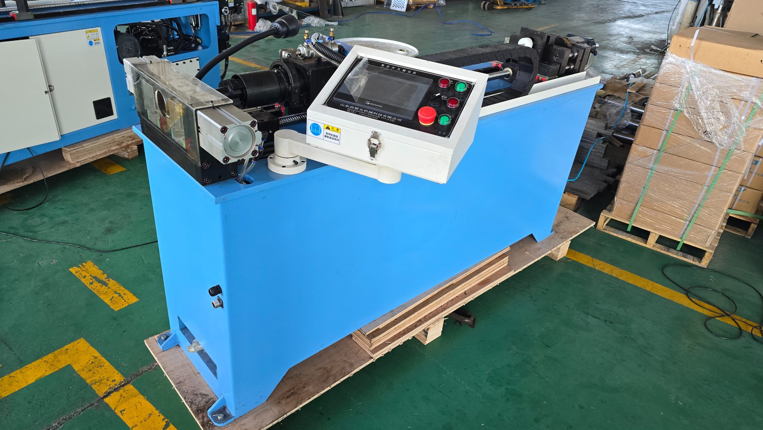
SINOAK equipment can be configured around defined coil families, from fin dies and fin press lines to copper tube straightening, hairpin bending, tube expansion, and supporting production steps. The useful starting data are product drawings, material specifications, output targets, product mix, factory layout, required quality checks, and the processes already in use.

For an initial discussion of line scope, equipment range, and technical support, contact SINOAK heat exchanger production equipment. The review can identify where a common process route is practical and where separate tools, fixtures, or handling controls are required for stable coil production.

FAQ

Can one HVAC coil line make both evaporators and condensers?

Often yes, when the required fin, tube, core, expansion, joining, and test ranges overlap. The decision should be based on the actual product-family matrix, changeover time, quality risk, and capacity, not the end-use name alone.

What data is most important before selecting coil equipment?

Provide representative and boundary drawings, fin and tube specifications, core dimensions, circuiting, pressure and test requirements, annual product mix, batch size, factory constraints, and the quality problems that the new equipment must reduce.

Conclusion

HVAC coil manufacturing is shaped by the product design as much as by the machine list. Group products by the parameters that change work content, select equipment against the boundary parts, and qualify fin, tube, expansion, joining, and test controls for each family. This creates a line that is flexible where it should be and controlled where it must be.

Добавить комментарий

Ваш адрес email не будет опубликован. Обязательные поля помечены *