Copper Tube Processing Equipment Guide
Steve
2026-09-10
Copper Tube Processing Equipment Guide
Copper tube processing equipment should be selected from the coil drawing, tube range, production mix, quality targets, and downstream process requirements. A collection of individually capable machines does not automatically become an efficient line. If cutting, bending, storage, tube insertion, and end forming are poorly connected, handling losses and quality variation can become more important than the nominal speed of any single machine.
For material properties, dimensions, and common joining practices, engineering teams can consult the Copper Tube Handbook. It is a useful technical reference when defining material and process boundaries, although machine trials with the actual tube remain essential before final acceptance.
The practical purchasing question is therefore not simply how many machines are required. It is where the process should be continuous, where flexibility must be preserved, and at which station each quality risk should be detected. This guide explains how to build that decision from the product backward.
Start With the Coil Drawing, Not the Machine List
Copper tube preparation affects tube insertion, mechanical expansion, return-bend assembly, brazing, and final leak performance. Before requesting a quotation, prepare a product boundary package that represents the full planned range rather than one typical coil.
- Tube material, outside diameter, wall thickness, coil weight, temper, and incoming condition.
- Hairpin straight length, total developed length, bend radius, center distance, and acceptable leg-height difference.
- Monthly demand by model, typical batch size, changeover frequency, and the product roadmap for the next two or three years.
- Downstream requirements for straightness, length, cleanliness, tube-end geometry, and traceability.
- Available floor space, operator skills, utilities, maintenance access, and the preferred level of automation.
|
Design input |
Processes affected |
Risk if omitted |
|
Tube diameter and wall |
Straightening, cutting, bending, expanding, end forming |
Incorrect clamping or tooling may create marks, ovality, wrinkles, or cracks. |
|
Hairpin length and bend radius |
Length feeding, cut-off, U-bending |
Machine travel or tooling range may not cover the complete product family. |
|
Batch size and changeovers |
Line integration, tooling, programs, material control |
Excess automation or long changeovers may reduce real output. |
|
Cleanliness and brazing rules |
Lubrication, washing, air blowing, storage |
Residue, contamination, and poor joint preparation can reach brazing. |

What Copper Tube Processing Equipment Should Include
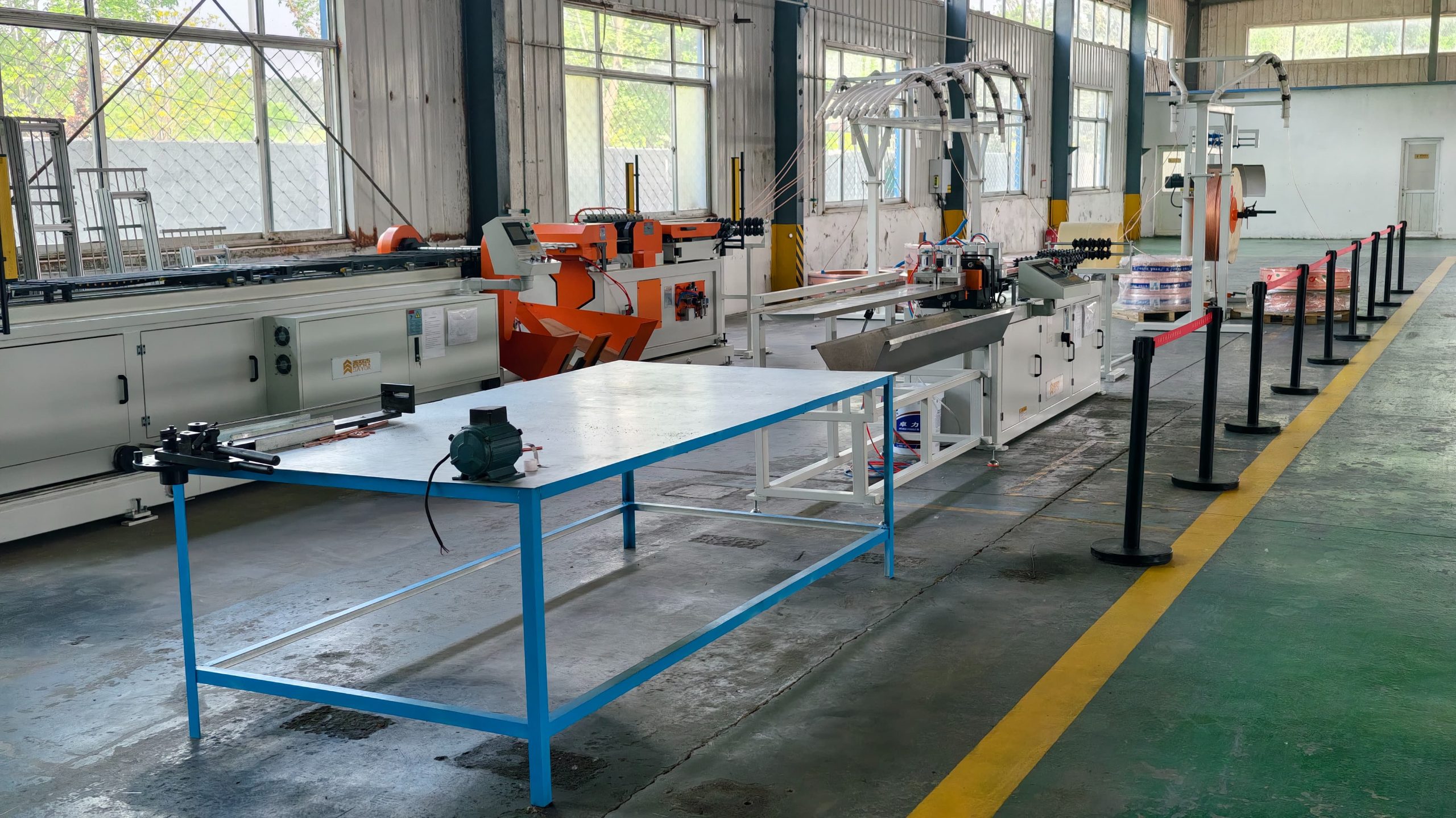
A fin-and-tube heat exchanger factory may use the following stations as separate machines or as integrated systems. The right boundary depends on product variety, required output, and how workpieces move into the next operation.
|
Equipment or station |
Main function |
Key purchasing points |
Downstream interface |
|
Tube straightening and cutting machine |
Uncoils, straightens, measures, and cuts copper tube to length |
Uncoiling resistance, straightener adjustment, feed accuracy, cut quality, burr control |
Length and straightness affect semi-automatic bending and tube insertion. |
|
Automatic hairpin bender |
Integrates uncoiling, straightening, length feeding, cutting, and U-bending |
Tube range, straight length, center distance, bend ovality, automatic discharge |
Produces hairpins that can move directly to insertion. |
|
Semi-automatic hairpin bender |
Bends pre-cut straight tubes into hairpins |
Loading method, locating repeatability, tooling change, small-batch efficiency |
Requires protected storage, transport, and manual loading of straight tubes. |
|
Return bender |
Produces small U-bends used to connect refrigerant circuits |
Diameter, center distance, cut end, wall thinning, cleaning |
Return-bend consistency affects fit-up and brazing. |
|
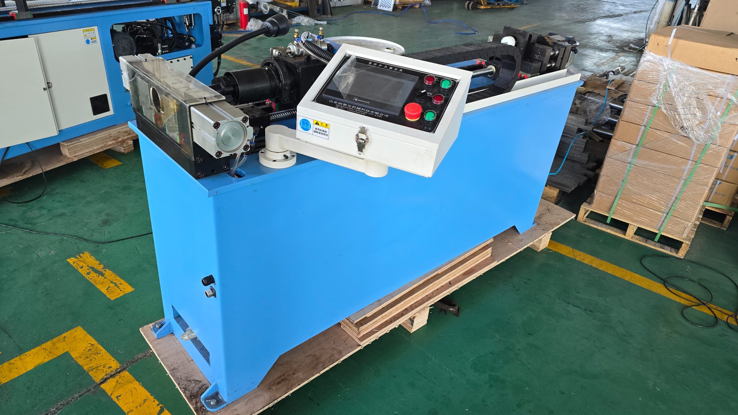
UBE punching and flanging machine |
Punches and forms branch collars in headers |
Hole pitch, collar height, header support, deformation control |
Controls branch-tube fit and brazing clearance. |
|
CNC spinning machine |
Forms tube-end expansions, reductions, beads, or compound profiles |
Profile accuracy, wall variation, concentricity, clamp marks |
Determines connector fit, sealing, and brazing stability. |
Automatic Hairpin Bender or Separate Machines?
Route A: integrated automatic hairpin bending
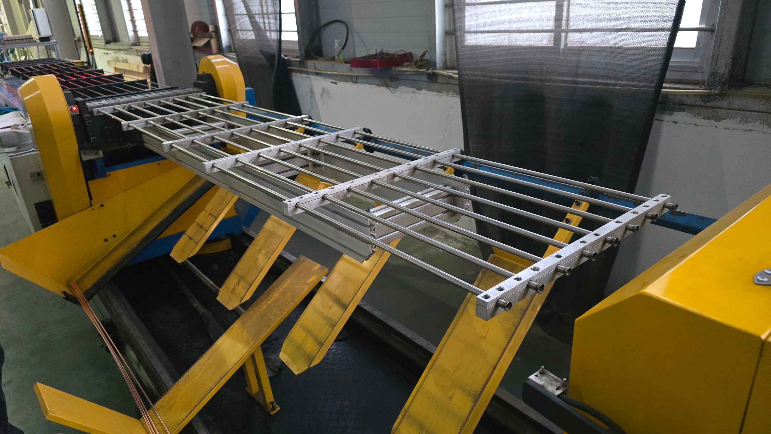
An automatic hairpin bender starts from coiled tube and continuously performs straightening, length feeding, cutting, and U-bending. Compared with a separate straightening and cutting machine plus a semi-automatic bender, it eliminates the transport, storage, and manual loading of long straight tubes. This reduces opportunities for scratches, secondary bending, mixed batches, and handling damage.
The integrated route normally fits stable product families and larger batches. However, the working range must cover diameter, wall thickness, straight length, center distance, and bend radius at the same time. A stated maximum length alone does not prove compatibility with the entire coil portfolio.
Route B: straightening and cutting plus semi-automatic bending
The separate route divides straight-tube preparation from U-bending. It is often suitable for small batches, multiple lengths, several tube diameters, prototype work, or phased investment. One straightening and cutting machine may also feed straight tubes to other operations besides hairpin production.
This flexibility adds material-handling requirements. Long tubes need supported racks or trays, controlled orientation, reliable identification, and a stable loading reference. Operators should not correct straightness or length by impact. Otherwise, the repeatability of the bending machine cannot be transferred to the finished hairpin.
|
Decision factor |
Integrated automatic route |
Separate-machine route |
|
Intermediate handling |
Low; no manual transfer or loading of long straight tubes |
Higher; racks, labels, handling standards, and deformation protection are needed. |
|
Changeover flexibility |
Depends on tooling and program design; frequent diameter changes need careful review |
Individual stations can be changed separately, which may suit varied small batches. |
|
Labor and flow |
Continuous process with lower dependence on manual feeding |
Buffers and manual loading must be balanced with upstream and downstream output. |
|
Traceability |
Continuous batch and parameter recording is easier to organize |
Trays, batch cards, or barcodes are needed to prevent mixed material. |
|
Investment logic |
Value becomes clearer when volume and process rhythm are stable |
Supports phased investment, but handling cost must be included. |
Calculate Required Capacity From Good Parts
Do not select copper tube machines only by their advertised maximum speed. Required capacity should be calculated from accepted parts. A simplified method is: shift demand divided by planned operating time, availability, performance efficiency, and first-pass yield. The coil demand must then be multiplied by the number of hairpins, return bends, or formed tube ends required in each product.
For example, two factories may both plan 500 coils per shift. If one coil uses 12 hairpins and the other uses 48, their hairpin demand differs by a factor of four. A quotation based only on finished coil quantity can therefore produce a serious capacity mismatch.
- Include coil changes, tooling changes, first-piece approval, cleaning, planned maintenance, and minor stops in the availability assumption.
- Verify cycle time for the shortest and longest products instead of using one ideal specification.
- Check tube-insertion capacity and intermediate buffer size so that high bender speed does not create work-in-process inventory.
- When one cutting machine supplies several stations, calculate peak combined demand rather than average consumption.
How Copper Tube Processing Equipment Fits the Line
Uncoiling and straightening: stabilize tension first
Coil diameter changes throughout uncoiling. If drag varies, the straightener receives a changing load and a previously acceptable roller setting may no longer produce stable straightness. Uncoiler braking, guide-roller path, tube center height, and the straightener entrance should be adjusted as one system.
Cutting and bending: length error becomes a hairpin error
Cut length, end squareness, and burr condition affect the final difference between the two hairpin legs. On a semi-automatic route, the straight tube also needs a defined datum end and loading direction. Feed error, cut error, and manual location error should be measured separately rather than hidden inside one compensation value.
Hairpin bending and insertion: judge quality at the next process
A U-shaped tube is not automatically a good hairpin. Leg parallelism, center distance, bend plane, end height, minimum bend section, and surface condition must match the fin-hole pattern and insertion method. If operators still need frequent manual correction before insertion, the acceptance criteria or machine settings require further work.

Common Quality Problems and Corrective Actions
|
Quality problem |
Likely causes |
Adjustment direction |
Verification |
|
Straight tube remains bowed |
Variable uncoiling tension; incorrect roller penetration; incoming coil variation |
Stabilize drag and guidance, then adjust roller groups progressively instead of overloading one point. |
Measure maximum deviation over a supported reference length. |
|
Periodic cut-length drift |
Feed-wheel slip; measuring-wheel wear; changing pull from the coil |
Clean feed surfaces, calibrate length measurement, and set clamping pressure for the actual tube. |
Measure consecutive samples at fixed intervals and review the trend. |
|
Burrs or flattened cut ends |
Worn tool; incorrect clearance; poor support; unsuitable cut speed |
Use a tooling-life and clearance standard by diameter and wall thickness; inspect support at the cut point. |
Check end face, inner and outer burr, and local ovality. |
|
Ovality or wrinkles at the U-bend |
Radius too small; unstable guidance; inconsistent lubrication; worn tooling |
Confirm the permitted radius, tooling profile, alignment, clamping, and lubrication amount. |
Measure the minimum section and conduct an insertion trial. |
|
Unequal or nonparallel legs |
Unstable datum; length error; tooling offset; discharge deformation |
Separate cut-length, bend-center, and unloading checks rather than applying one general offset. |
Use a fixture to measure center distance, leg height, and parallelism together. |
|
Scratches or uneven oil |
Dirty guides or trays; excessive clamping; unstable lubrication |
Identify whether damage occurs inside the machine or during handling, then correct the specific contact point. |
Use controlled lighting and a visual standard; trace the first station where damage appears. |
Evaluating a Practical SINOAK Configuration
A useful evaluation should combine machine range, product trials, process integration, and technical support. SINOAK copper tube equipment can be configured around straightening and cutting, automatic or semi-automatic hairpin bending, return-bend production, UBE punching and flanging, and CNC tube-end forming. For stable high-volume work, an automatic hairpin bender can remove the handling and manual loading of pre-cut straight tubes. For varied small batches, separate machines may preserve more changeover flexibility.
To discuss a configuration from coil drawings, tube range, shift output, and available floor space, use the SINOAK heat exchanger production equipment and technical support page as the confirmed internal reference. A useful request should include representative drawings, demand by model, quality limits, and the intended process route.
The benefit of a proposed system should not be reduced to higher speed. The operating range must cover the real product matrix; tools and programs should support practical changeovers; and commissioning plus operator training should help the factory establish stable parameters. Final confirmation should still be based on representative trials and agreed acceptance criteria.
Information to Prepare Before Requesting a Quotation
- Complete tube range: material, outside diameter, wall thickness, temper, coil weight, and incoming condition.
- Representative drawings covering the shortest, longest, smallest-radius, and most frequently changed products.
- Coils per shift, hairpins per coil, number of shifts, expected OEE, and planned expansion.
- Critical quality characteristics and measurement methods for length, straightness, center distance, ovality, burrs, and scratches.
- Upstream and downstream machine positions, cycle times, transfer height, and planned buffering method.
- Factory dimensions, electrical supply, compressed air, chip or oil control, and maintenance clearance.
- Operator count, skill level, parameter-access rules, preferred interface language, and training expectations.
- Acceptance samples, sampling quantity, continuous-run duration, changeover test, and spare-parts scope.
FAQ
Does an automatic hairpin bender eliminate the need for a straightening and cutting machine?
Should a low-volume, high-mix factory always choose semi-automatic equipment?
How should hairpin bending quality be accepted?
Why can a high-speed machine still leave the line short of parts?
Which samples should be used for machine acceptance?
Conclusion
Copper tube processing equipment has no universal configuration. Stable, concentrated production may justify integrated automatic hairpin bending because it reduces handling, storage, and manual feeding. High-mix work or phased investment may favor separate straightening, cutting, and bending stations, provided material flow and traceability are properly controlled.
A sound decision must satisfy three measurable conditions: the equipment range covers the product matrix, process interfaces do not introduce new quality risks, and good-part capacity meets the plan under realistic changeovers and downtime. Drawings, representative trials, and accepted cycle-time data should demonstrate all three before the order is finalized.
Recent News