How to Improve Heat Exchanger Production Efficiency
Steve
2026-09-23

How to Improve Heat Exchanger Production Efficiency
Heat exchanger production efficiency improves when a factory measures the complete route from incoming fin stock and copper tube to tested coil, rather than chasing the highest speed on one machine. For a structured approach to flow and continuous improvement, review NIST MEP lean and process improvement guidance. The final improvement plan must be based on the plant’s product mix, constraints, and verified quality requirements.
A fin-and-tube coil line loses output through waiting, poor changeovers, handling, unstable settings, minor stops, rework, and uneven work-in-process. These losses interact. Increasing fin press speed, for example, cannot improve shipment when tube expansion, brazing, leak testing, or coil handling is the real limit.
The useful target is sustained conforming output: coils that meet the drawing, pass required tests, and are available to the next process without hidden rework. This guide shows how to locate the limiting process and improve it without sacrificing fin, tube, joint, or test quality.
Define heat exchanger production efficiency correctly
|
Measure |
What it answers |
Use in a coil factory |
Common error |
|
Conforming output |
How many accepted coils leave the route |
Links capacity with quality and delivery |
Counting pieces before rework or test |
|
Cycle time |
How long one process actually takes |
Shows the load at fin pressing, bending, expansion, brazing, and testing |
Timing machine motion but not loading or inspection |
|
OEE |
Where availability, speed, and quality are lost |
Separates failures, minor stops, slow cycles, and rejects |
Using one assumed OEE for every station |
|
First-pass yield |
How much output clears a process without correction |
Makes handling, tooling, and parameter losses visible |
Treating rework as normal output |
|
WIP age and quantity |
How much material waits between stations |
Reveals imbalance, search time, and mix-up exposure |
Believing more WIP always protects delivery |
Use the same product definition and time period for every measure. A shift report that compares fin count at the press with finished-coil count at test can be useful, but it does not identify the process loss until the required work content and quality release are connected.

Find the bottleneck before increasing machine speed
The bottleneck is the resource that limits finished shipments under the current schedule. It may move with the product mix. Long hairpins may constrain bending, coils with many tube holes may constrain expansion, and high-pressure products may constrain stabilization and leak-test time.
- Convert demand for each product family into fin, tube, hairpin, expansion, brazing, and test workload.
- Include loading, unloading, inspection, material waiting, changeover, and common abnormal recovery time.
- Compare required machine hours with available machine hours by station, not only average line output.
- Check the most heavily loaded period and boundary products instead of relying on the average coil.
- Improve the active bottleneck first, then remeasure because the constraint may move to another station.
A faster non-bottleneck station usually creates more work in process, extra handling, and less visible quality risk. The right improvement removes a verified constraint or protects the constraint from upstream and downstream interruptions.
Improve heat exchanger production efficiency at each process
|
Process |
Frequent efficiency loss |
Practical improvement |
Quality condition |
|
Fin stamping |
Coil change, material misfeed, die jam, scrap collection, and unstable lubrication |
Standardize coil setup, maintain guides and die, and control material and lubrication windows |
Use sustained conforming press speed, not a short trial peak |
|
Tube straightening and bending |
Feed slip, length adjustment, tube support, manual unloading, and product switching |
Separate feed, bend, unload, and inspection losses; add support and repeatable settings |
Confirm length, bend geometry, surface condition, and end shape |
|
Lacing and assembly |
Searching, fin damage, difficult insertion, and uneven operator workload |
Use product-specific fixtures, clear WIP locations, and balanced tube supply |
Protect fin holes and tube surfaces while improving access |
|
Tube expansion |
Slow loading, wrong recipe, rod wear, clamping adjustment, and rework |
Store verified recipes, organize tools, and improve positioning before shortening the process cycle |
Keep the qualified force, stroke, and hold-time window |
|
Brazing and test |
Waiting for fixtures, connector replacement, retest, and unclear defect routing |
Prepare joints and fixtures, record common failures, and balance stabilization and inspection |
Do not shorten test time below the qualified method |
Reduce changeover without losing product control
High-mix coil production can lose more output in changeover than in machine running time. A useful changeover program separates tasks that can be prepared while the machine is still running from tasks that must occur after the last good part. It also makes tooling, parameters, first-piece approval, and material identification visible.
- Record the current changeover with start and finish times, including searching, cleaning, adjustment, and approval.
- Separate external preparation from internal machine-stop work, then move practical preparation outside the stop window.
- Create a controlled set of dies, guides, bending tools, expansion rods, fixtures, recipes, and gauges for each family.
- Define first-piece acceptance measurements and ownership before the machine changes product.
- Trial the new method with boundary models and record the stable time, defects, and recovery requirements.
Use OEE as a loss map, not a target by itself
OEE is valuable when it leads to specific action. Availability losses need reason codes that distinguish failures, material waiting, quality holds, planned changes, and service. Performance losses need a qualified ideal cycle for each product family. Quality losses need first-pass output, rework, scrap, and the defect source.
|
Loss pattern |
Likely root cause |
Improvement direction |
|
Frequent short stops |
Unstable feeding, sensor position, worn guides, or inconsistent material |
Classify the stop, verify mechanical datum and material condition, then adjust parameters |
|
Slow running after startup |
Operators reduce speed to control an unresolved quality issue |
Define the stable quality window and correct the underlying tooling, support, or material cause |
|
High retest or rework |
Test connections, process parameters, cleaning, or handling cause variation |
Trace defects to product, station, and condition; correct the first harmful contact or parameter |
|
Long waiting between stations |
Imbalanced load, unclear priority, excessive batch size, or unsafe handling route |
Balance the constraint, set WIP limits, and standardize FIFO and transfer method |

Control WIP, handling, and information flow
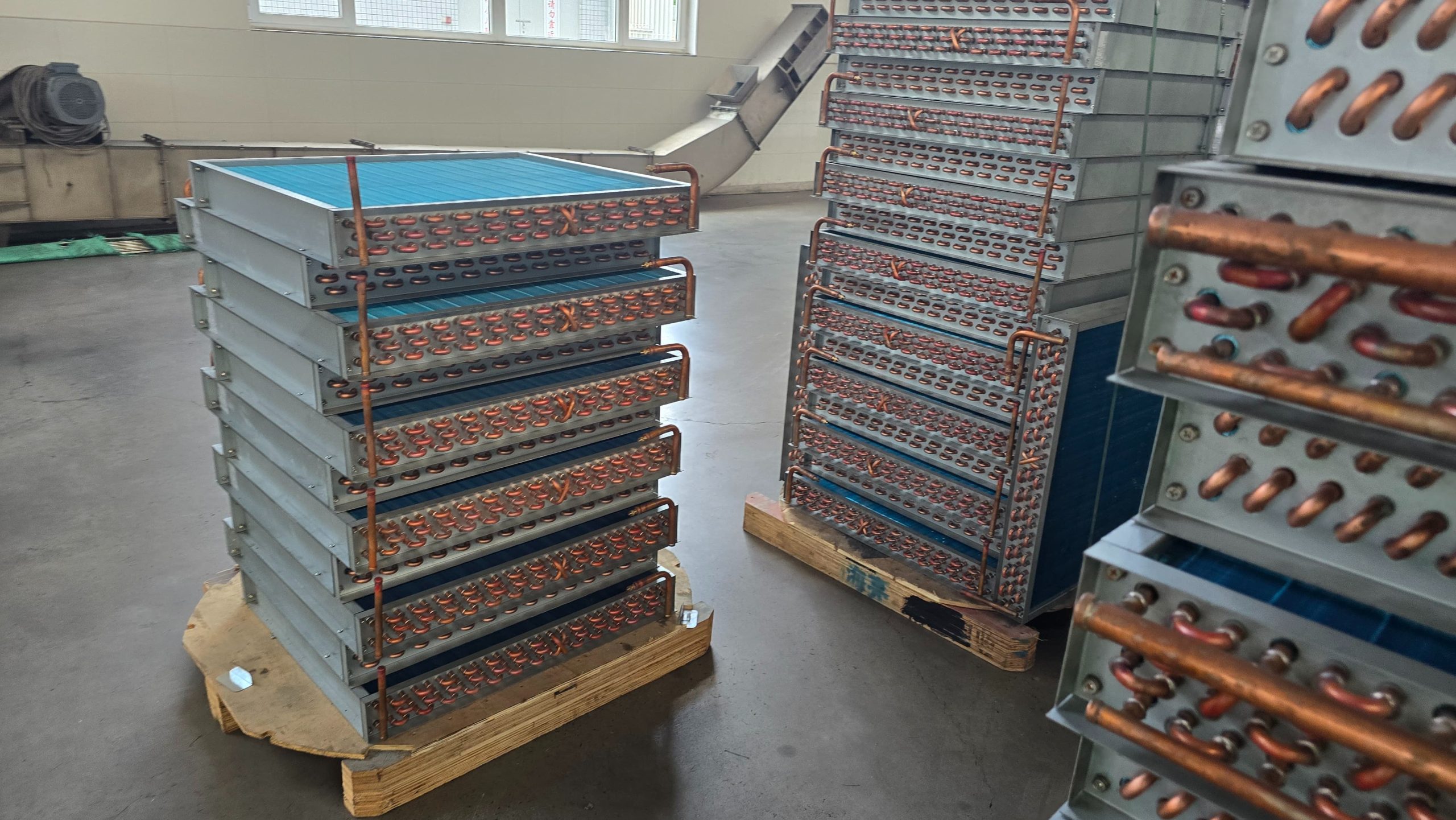
Work in process should protect a short interruption, not conceal a permanent imbalance. Uncontrolled fin stacks, hairpin racks, and completed cores add searching, mix-ups, and handling damage. Each buffer needs a defined location, maximum quantity, product status, and first-in first-out rule.
- Use a visible location for released, hold, rework, and awaiting-inspection coils.
- Keep product identity with the coil or carrier through every manual and automatic handoff.
- Support long tubes and fin packs at defined contact points; do not use fragile surfaces as convenient supports.
- Measure queue age and reason for waiting, not only total pieces in the factory.
- Reduce travel and crossing before adding more inspection or manual transfers.
Common quality problems when output is pushed too hard
|
Problem |
Why it appears |
Adjustment and optimization |
|
Fin misfeed, damaged holes, or die jams |
Press speed or feed settings exceed the stable die and material window |
Restore stable feed and lubrication, inspect guides and die condition, then verify sustained speed |
|
Hairpin length drift or surface scratches |
Feeding, tube support, or unloading cannot keep pace with the commanded cycle |
Improve tube support and unloading; set the cycle from complete conforming work |
|
Under-expansion, over-expansion, or core distortion |
Critical positioning, clamping, or hold time is shortened to gain output |
Keep qualified expansion parameters; improve loading, tool preparation, and error-proofing separately |
|
Brazing leaks or unstable test results |
Joint preparation, connector condition, stabilization, or test routing is rushed |
Control cleanliness and fixtures, maintain connectors, and trace retest cause before reducing test time |
|
Coil damage between stations |
Excess WIP, point contact, unsupported tubes, or unplanned forklift movement |
Define carriers, support points, and FIFO routes; remove the first damaging contact |
Plan equipment upgrades around the real constraint
An equipment upgrade should state which loss it removes and how acceptance will prove the result. Faster machine motion alone is insufficient. The proposal should include representative product dimensions, loading and unloading time, changeover, expected conforming cycle, utilities, operator actions, maintenance access, and the interface to adjacent processes.
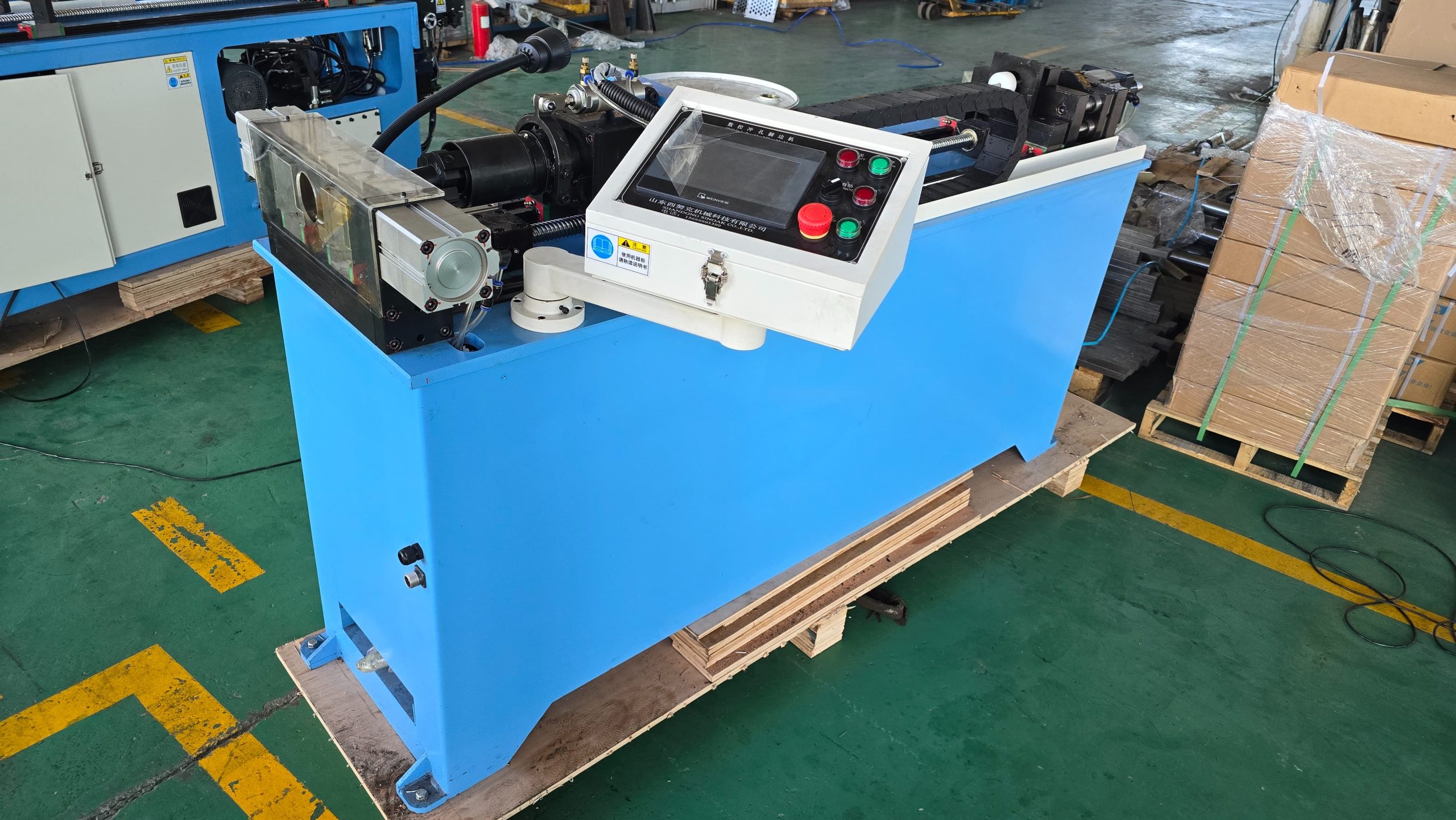
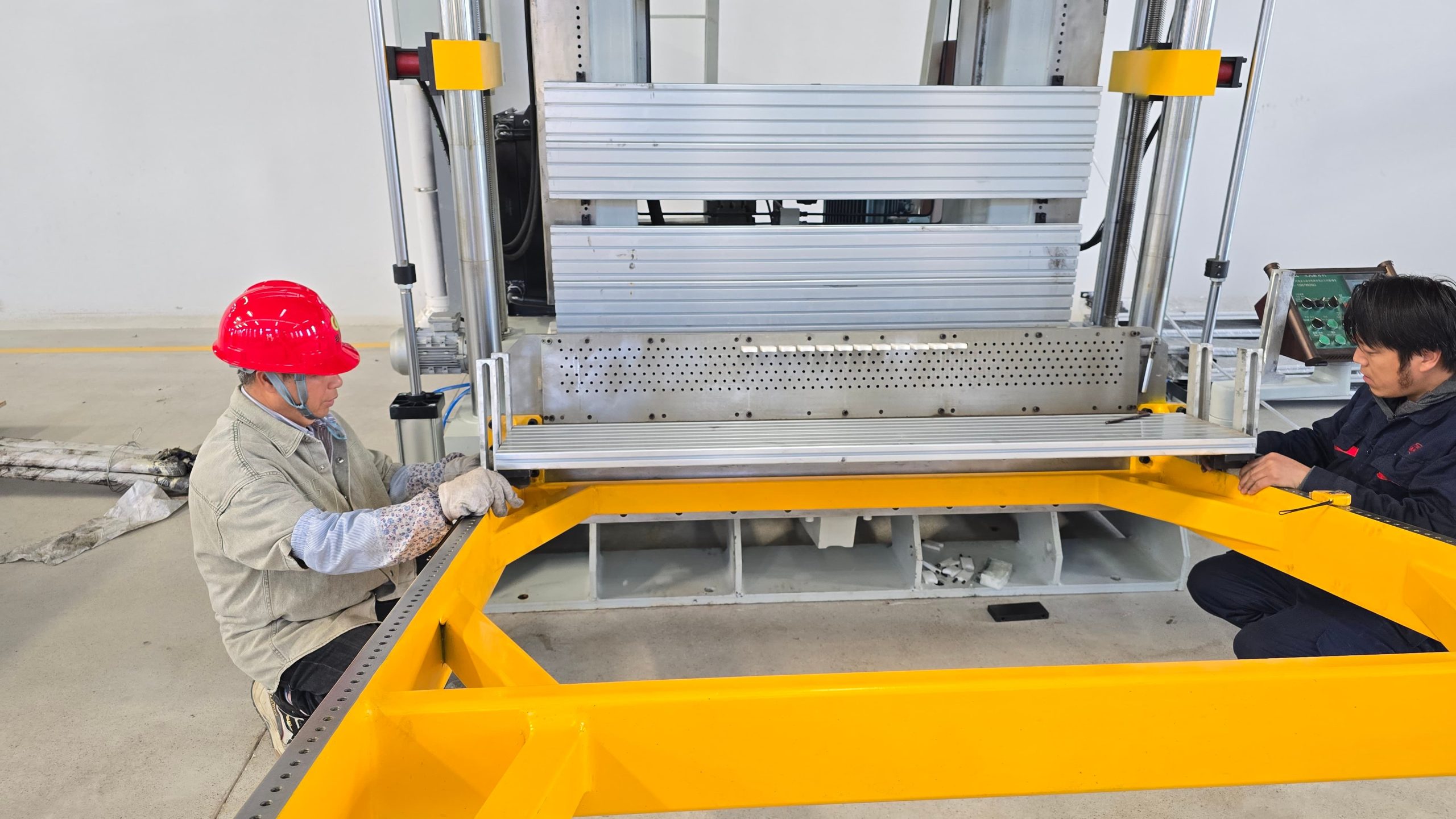
For production-line planning that connects fin processing, copper tube preparation, expansion, and supporting workstations, review SINOAK heat exchanger production equipment and technical support. SINOAK can assess product drawings, production demand, process sequence, and current loss data to align equipment configuration with the factory’s practical efficiency target.
For phased expansion, prioritize infrastructure and interfaces that are difficult to add later: material routes, safe handling space, electrical capacity, compressed air, tooling storage, data connections, and access for die or expansion-rod changes.
A practical 30-day improvement cycle
- Choose one product family and map its actual route from material release to tested coil.
- Measure cycle, waiting, changeover, downtime, first-pass yield, and WIP at every process.
- Confirm the active bottleneck with mixed-product load rather than a single-machine observation.
- Correct one repeatable loss with an owner, deadline, controlled trial, and quality check.
- Standardize the successful method in the fixture, setup sheet, recipe, route, or maintenance task.
- Remeasure the result and select the next constraint instead of assuming the same station remains limiting.
FAQ
What is the first efficiency metric to track?
Should a factory buy a faster machine to improve output?
Conclusion
Heat exchanger production efficiency comes from stable, balanced, and visible work rather than maximum speed at isolated machines. Measure conforming output, identify the real bottleneck, reduce changeover and waiting, protect fins and tubes during transfer, and correct repeatable quality losses at their source. This approach improves delivery without making the process harder to control.
Recent News