Complete Selection Guide for Vertical Tube Expander Machines in HVAC Coil Manufacturing

Complete Selection Guide for Vertical Tube Expander Machines in HVAC Coil Manufacturing

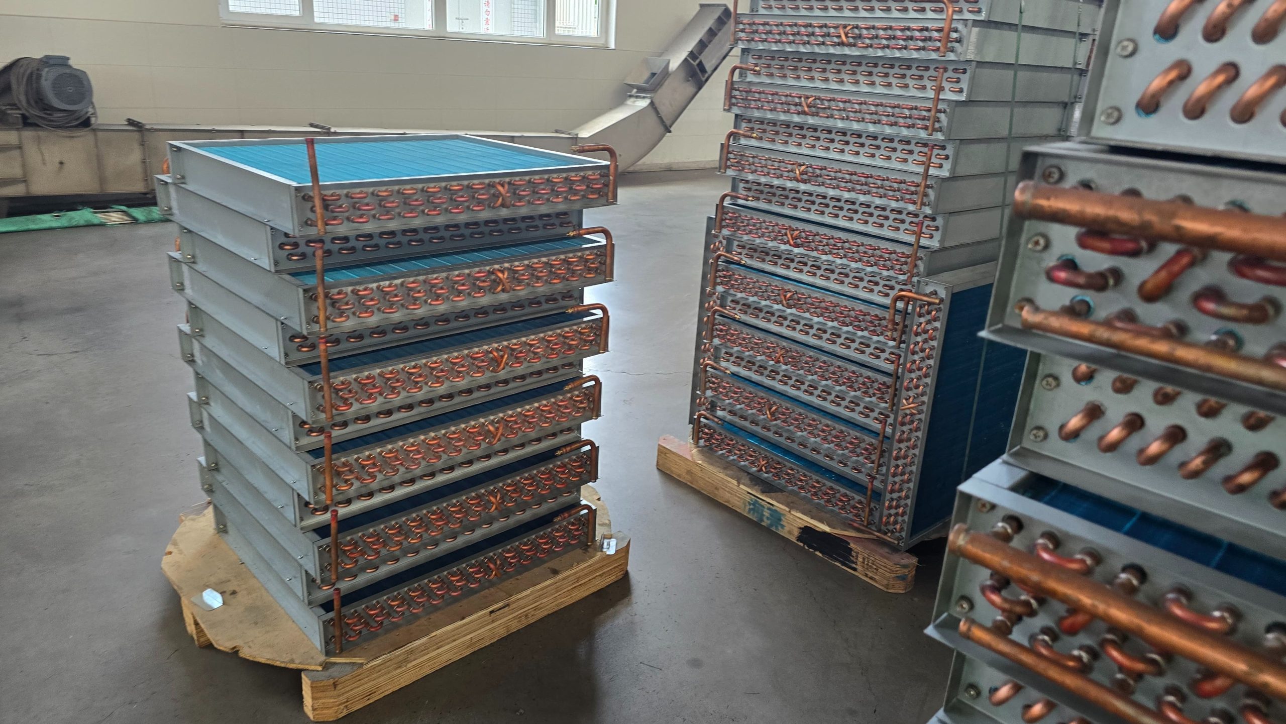
In finned tube heat exchanger manufacturing, achieving maximum thermal transfer efficiency relies heavily on the quality of mechanical bonding between the tubes and fin collars. Specifically, after hairpin tubes are laced through the stamped fin matrix, a Vertical Tube Expander Machine drives mechanical bullet mandrels through the interior of the tubes. As a result, this action expands them outward into a precision interference fit with the fin collars.

Currently, vertical tube expanders are widely preferred for medium-to-large production runs of residential and commercial evaporators, condensers, and unit coolers. This is mainly due to their minimal floor space footprint, fast setup times, and superior gravity-assisted coil alignment.

Therefore, this comprehensive engineering guide explores the mechanical principles, structural drive architectures, quality control mechanisms, maintenance procedures, and technical RFQ checklists needed when specifying a vertical tube expander for your facility.

1. Core Functions and Process Breakdown

Unlike horizontal expansion systems that require extensive floor space to accommodate long drive rods, a vertical tube expander utilizes overhead vertical stroke motion. Specifically, the machine completes four automated stages during a single cycle:

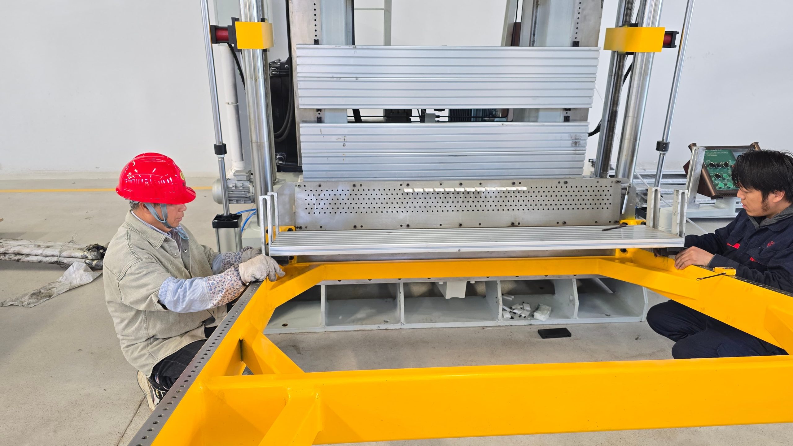
  • Stage 1: Coil Loading and Clamping: First, the laced coil block is loaded vertically into the machine frame. Simultaneously, pneumatic or hydraulic side-clamping jaws secure the fin pack to prevent fin distortion during the stroke.

  • Stage 2: Bottom Flare and End Sizing: Next, bottom tooling clamps the tube ends, preparing them with precise bell expansions or flares for subsequent return bend brazing.

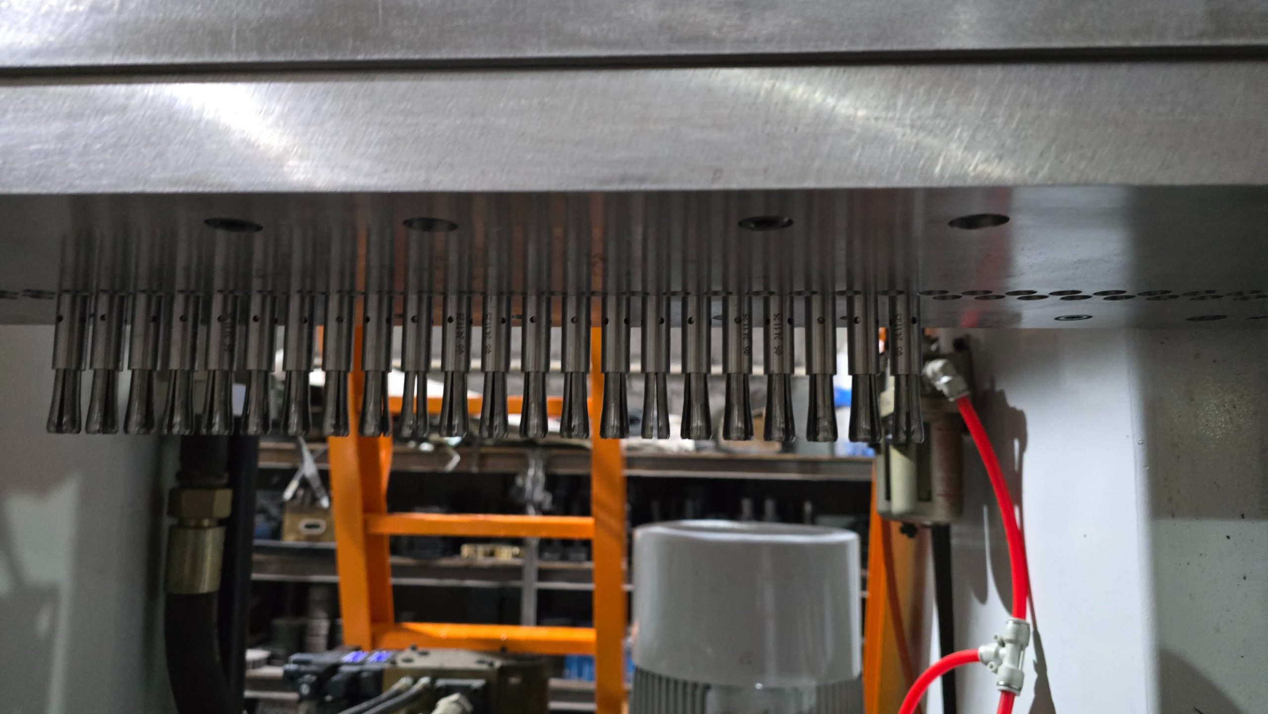
  • Stage 3: Mandrel Expansion Stroke: Following this, overhead expansion rods equipped with hardened tungsten carbide bullet mandrels travel downward through the tube interior. Consequently, this process expands the metal wall outward to eliminate contact thermal resistance.

  • Stage 4: Mandrel Retraction and Unclamping: Finally, the expansion rods retract upward, and then the machine releases the coil block for unloading or automatic transfer to downstream assembly stations.

2. Technical Comparison: Drive Systems and Table Architectures


In practice, choosing the right drive system and table layout directly impacts positioning accuracy, cycle speed, energy efficiency, and overall productivity.

Drive System Comparison: Hydraulic vs CNC Servo Drive
Performance MetricHydraulic Vertical ExpanderCNC Servo-Driven Vertical Expander
Drive MechanismHeavy-duty hydraulic cylinders and power unitHigh-torque AC Servo Motors and precision ball-screws
Expansion Speed ControlControlled via proportional hydraulic valvesDigitally programmed via HMI with variable speed curves
Positioning PrecisionPlus or minus 0.5 mm (Adjusted via limit switches)Plus or minus 0.02 mm (Absolute encoder feedback)
Energy ConsumptionContinuous hydraulic pump operationOn-demand power draw (Up to 35% energy savings)
Oil Contamination RiskRequires thermal monitoring; risk of fluid leaksZero oil leaks; cleaner factory environment
Best Suited ForHigh-tonnage, heavy-wall industrial coil expansionUltra-thin wall, high-precision micro-groove coils
 
Table Setup Comparison: Single-Station vs Dual-Station Shuttle Table


Operating FeatureSingle-Station LayoutDual-Station Shuttle Table Layout
Operator EfficiencyOperator waits during expansion strokeLoading/unloading happens simultaneously with stroke
Line ProductivityBaseline throughputUp to 40% higher throughput
Factory FootprintCompact floor space requiredSlightly wider machine bed required
Initial Capital InvestmentLower equipment costHigher initial cost with rapid ROI

3. Quality Defect Prevention and Process Control

During high-speed vertical expansion, improper machine settings or worn tooling can lead to severe coil defects. However, understanding how modern machines prevent these issues is crucial for maintaining zero-defect production:

Defect 1: Tube Wall Splitting and Over-Expansion
  • Primary Cause: This typically happens due to excessive bullet clearance or inconsistent tube wall thickness.

  • Effective Prevention: To solve this, CNC servo expanders utilize real-time torque and load monitoring. For instance, if resistance exceeds safety thresholds, the stroke automatically pauses, thereby preventing tube rupture and costly die damage.

Defect 2: Fin Buckling and Collar Flattening
  • Primary Cause: This is usually caused by inadequate or uneven side clamping force on the fin stack during the downward stroke.

  • Effective Prevention: In order to fix this, synchronized hydraulic or servo side-clamping plates ensure uniform lateral pressure across the entire coil face length before the mandrels enter the tubes.

Defect 3: Micro-Groove Internal Ridge Damage
  • Primary Cause: This occurs when pushing hard carbide bullets at fixed high speeds through delicate spiral-grooved copper tubes.

  • Effective Prevention: Instead, multi-stage variable expansion speed curves slow down mandrel velocity during initial entry and final exit, thus preserving internal micro-fin heat transfer geometry.

4. Equipment Maintenance and Operational Lifecycle

In addition, to guarantee a long operational lifespan and minimize unplanned downtime, routine preventive maintenance should be integrated into your production workflow:

Maintenance IntervalTarget Component / TaskOperational Objective
Daily (Per Shift)Inspect and clean bullet mandrels; check lubrication spraysPrevents copper galling and scratches inside tubes
WeeklyCheck expansion rod straightness and clamping jaw alignmentEnsures even expansion force across all tube rows
MonthlyInspect ball-screws (Servo) or check hydraulic fluid qualityMaintains stroke positioning precision and speed control
Quarterly / AnnualReplace worn expansion bullets, O-rings, and rod guide bushingsRestores factory tolerance and prevents tolerance drift

5. Application Matching Matrix

Overall, the choice of machine configuration depends heavily on your specific product application:

Heat Exchanger ApplicationTypical Tube ODTypical Coil LengthRecommended Machine Configuration
Residential Split AC / Heat Pump5 mm, 7 mm, 9.52 mm400 mm to 1200 mmDual-Station CNC Servo Vertical Expander
Commercial Air Coolers / Condensers9.52 mm, 12.7 mm1000 mm to 2500 mmHydraulic or Servo Vertical Expander with Shuttle Table
Industrial Freezing / Cold Storage12.7 mm, 15.88 mm1500 mm to 3000 mm+High-Tonnage Hydraulic Vertical or Horizontal Expander

Summary: Equipment Selection and RFQ Technical Checklist

In conclusion, specifying the correct vertical tube expander machine requires matching your heat exchanger block dimensions and tube parameters with the machine’s tonnage and stroke capabilities.

To begin this process, please review and share the following specifications with your inquiry so our technical engineering team can design a custom vertical tube expander and prepare an itemized quote:

RFQ Technical Information Checklist:

  1. Tube Specifications:

    • Tube material (Copper, Aluminum, CuNi, or Stainless Steel)

    • Tube Outer Diameter (OD) options (e.g., 5 mm, 7 mm, 9.52 mm, 12.7 mm, 15.88 mm)

    • Tube wall thickness and inner surface geometry (Smooth bore or Micro-grooved)

  2. Coil Block Dimensions:

    • Maximum and minimum coil face length (e.g., 300 mm to 2500 mm)

    • Maximum coil height (Width across fins) and maximum tube row depth (e.g., 1 to 8 rows)

    • Fin pattern matrix (e.g., 25 x 21.65 mm, 31.75 x 27.5 mm, 38 x 32.99 mm)

  3. Capacity and Machine Setup:

    • Target production output per 8-hour shift

    • Drive architecture preference (Hydraulic vs Full CNC Servo)

    • Shuttle table setup preference (Single station vs Dual-station indexing shuttle)

  4. Plant Facility Utilities:

    • Maximum available factory ceiling height clearance

    • Power supply specifications (e.g., 380V / 50Hz / 3-Phase)

    • Compressed air pressure and pneumatic supply availability

As a specialized engineering manufacturer of complete HVAC&R machinery—including high-speed fin press lines, custom fin dies, automatic hairpin benders, and vertical/horizontal tube expanders—SINOAK delivers complete production solutions tailored to your technical requirements.

Therefore, we invite you to contact our engineering support team today with your coil technical drawings to receive a free plant layout consultation, process analysis, and customized machinery proposal!
Leave a Reply

Your email address will not be published. Required fields are marked *