Progressive Fin Die Selection and Engineering Guide for Coil Makers
Steve
2026-10-16
HVAC Coil Manufacturing Differences by Product and Process
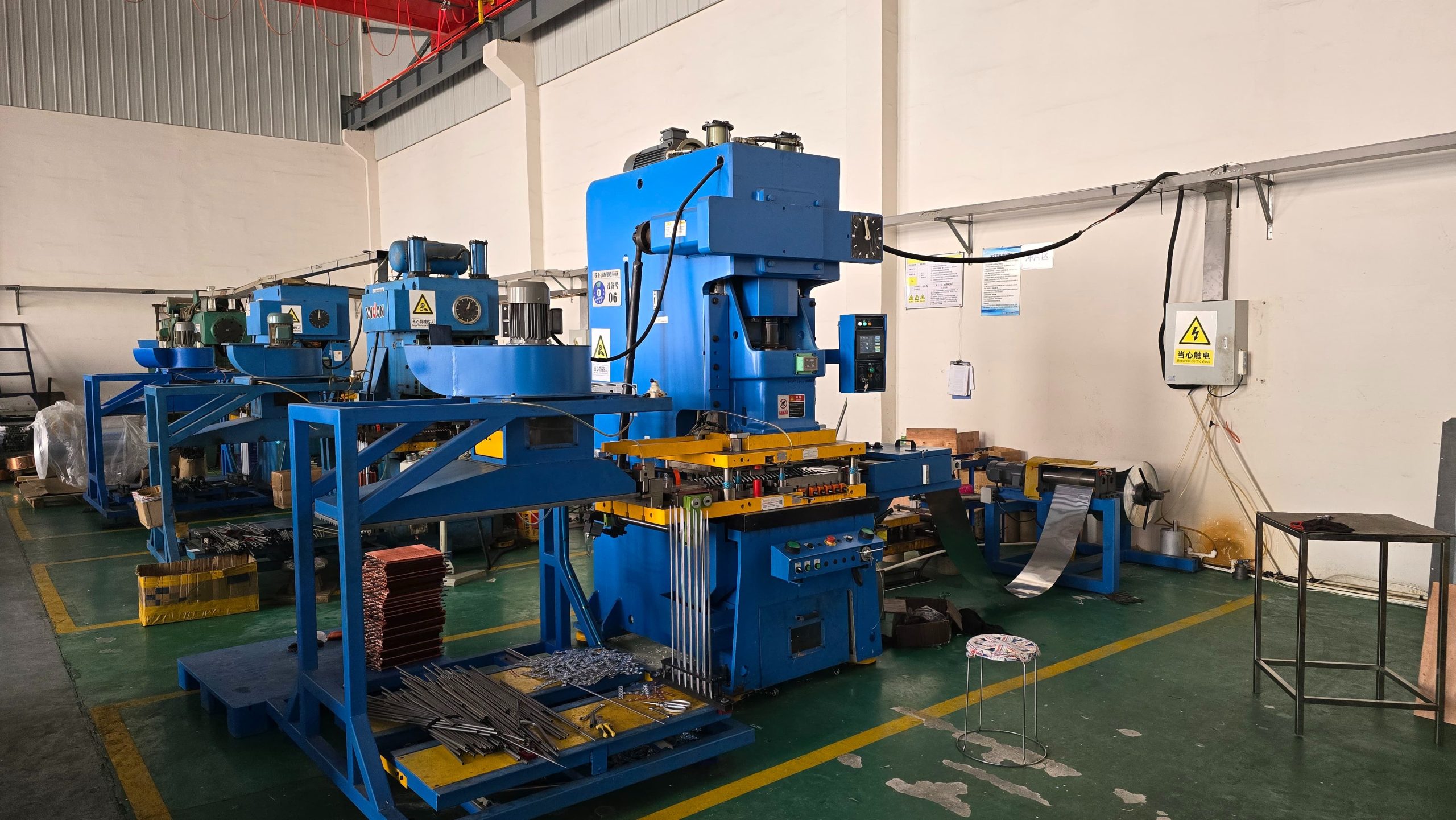
In heat exchanger manufacturing, the progressive fin die is the single most critical tooling investment on the press line. Operating at hundreds of strokes per minute, a high-precision fin die performs complex, multi-stage cold forming on aluminum or copper foil. Specifically, it punches tube holes, draws collar heights, forms turbulent louver patterns, and shears fin strips to length in a single continuous press cycle.
Currently, as HVAC OEMs demand thinner foil stock and higher collar consistency to accommodate low-GWP refrigerants, tooling precision becomes paramount according to international AHRI standards. Therefore, this engineering guide provides a deep technical analysis of progressive fin die mechanics, carbide material selection, surface geometry optimization, coating protection, and wear mitigation for new tooling procurement.
Precision Mechanics of Progressive Fin Forming
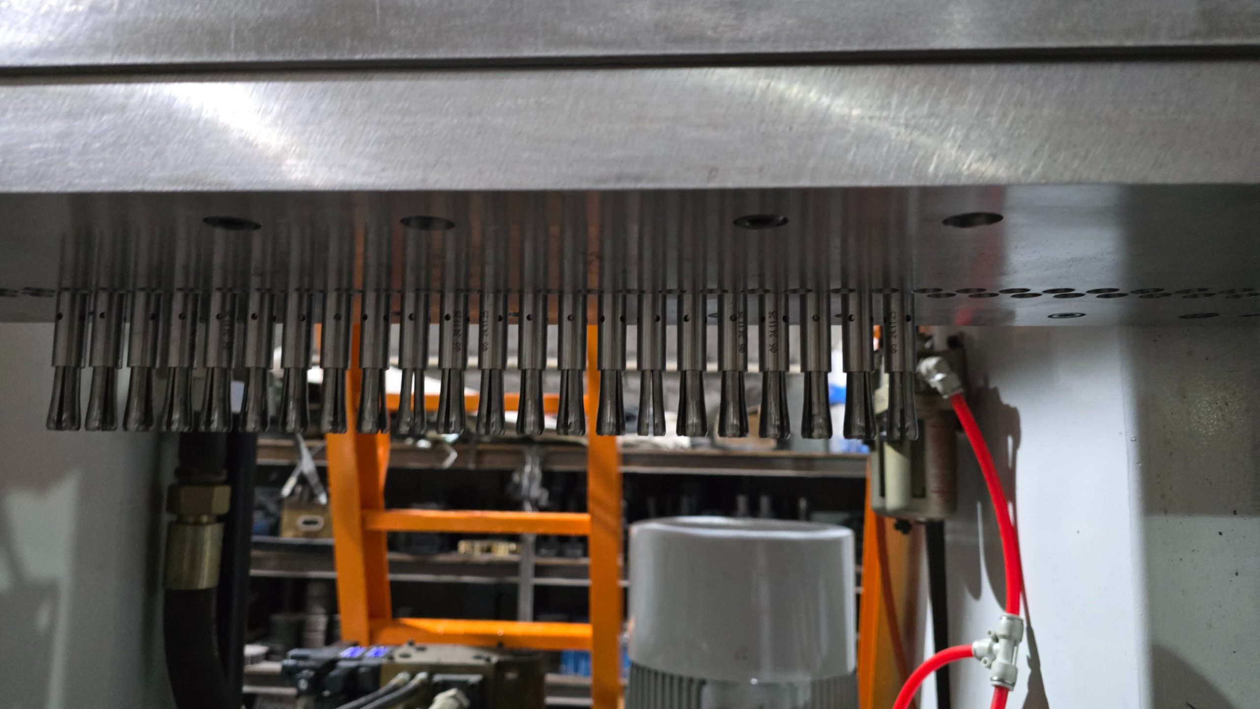
A high-speed progressive fin die houses multiple inline workstations, each performing a dedicated step as the foil ribbon advances through the press bed:
-
Piercing and Hole Preparation: First, precision punch pins pierce the initial pilot holes through the aluminum ribbon. Simultaneously, side-piloting stations lock the material alignment to ensure pitch accuracy across all rows, preparing the fins for downstream processing on a High-Speed Fin Press Line.
-
Collar Drawing and Flanging: Next, multi-stage draw punches stretch the metal outward to form high-standing collar rims. In addition, special iron-forming rings maintain uniform wall thickness, preventing collar splits during expansion.
-
Louver and Wave Corrugation: Following this, upper and lower forming inserts stamp louver vents or sinusoidal wave patterns onto the fin surface. As a result, these geometric features break boundary air layers and maximize convective heat transfer.
-
Slitting and Cut-off: Finally, rotary slitting knives cut the continuous ribbon into designated fin widths, and then high-speed cut-off blades sever the fins to exact leg lengths.

Material Selection and Structural Durability
In practice, the longevity of a progressive fin die depends heavily on the quality of steel alloys and carbide inserts selected for high-wear components.
| Component Part | Recommended Tooling Material | Engineering Function and Benefit |
| Punch Pins and Draw Insets | Micro-grain Tungsten Carbide | Exceptional hardness; prevents galling during continuous high-speed drawing |
| Die Plates and Matrix | SKD11 or DC53 Tool Steel | Superior dimensional stability; resists micro-cracking under heavy shock loads |
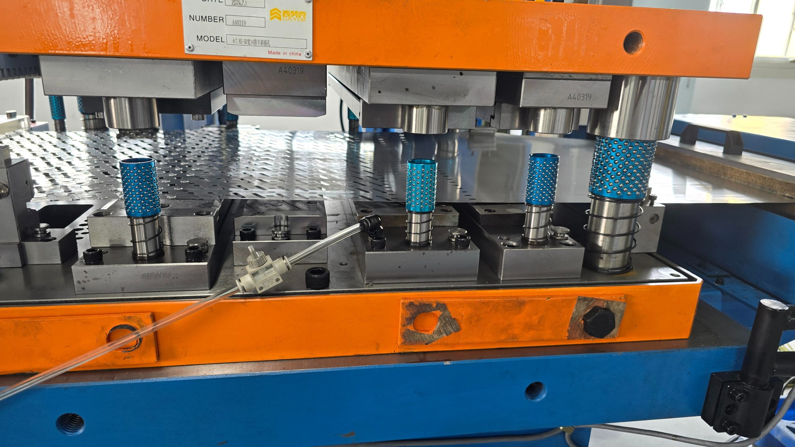
| Guide Pillars and Bushings | Ball-bearing Alloy Steel Assembly | Eliminates lateral play; preserves sub-micron alignment between top and bottom dies |
| Stripper Plates | High-tensile Alloy Steel | Ensures clean, distortion-free ejection of thin foil stock after every stroke |
Stamping Mechanics for Hydrophilic and Coated Foil
Additionally, modern evaporators increasingly utilize hydrophilic, hydrophobic, or epoxy-coated aluminum foil to prevent condensate water bridging and enhance corrosion resistance. However, processing coated foil stock introduces unique tooling challenges during high-speed stamping:
Coating Flaking and Dust Accumulation
-
The Engineering Challenge: During rapid drawing operations, the outer resin or hydrophilic layer can flake off under intense shear stress, creating fine coating dust inside the die cavity. Consequently, this powder accumulates around collar draw stations, leading to dimensional tolerance drift.
-
Tooling Solutions: To mitigate this issue, progressive fin dies engineered for coated foil feature polished micro-clearance draw rings, air-blow dust removal ports, and vacuum extraction channels. As a result, these elements purge debris in real time, preventing dust buildup.
Surface Scratch Prevention and Micro-Slick Tooling
-
The Engineering Challenge: Scratches on epoxy-coated fins expose bare aluminum to corrosive environments, compromising coil durability in coastal regions.
-
Tooling Solutions: Instead of standard steel, high-wear contact surfaces utilize Titanium Nitride (TiN) or Diamond-Like Carbon (DLC) physical vapor deposition coatings. Therefore, this drastically lowers friction coefficients and prevents coating abrasion during the collar drawing stroke.
Surface Geometry and Aerodynamic Optimization
The thermal efficiency of a heat exchanger coil is intrinsically tied to the surface features stamped by the progressive fin die. Specifically, tooling engineers balance thermal enhancement against air-side pressure drop through optimized die station profiles:
Louvered Fin Configurations
-
Thermal Dynamics: Louver angles typically range from 18 to 28 degrees. By slicing the air stream, louvers disrupt the thermal boundary layer, increasing the convective heat transfer coefficient significantly.
-
Tooling Execution: High-precision shearing punches create narrow louver slats with zero burrs, maintaining clean airflow passages to reduce fan power consumption.
Sine Wave and Wavy Fin Patterns
-
Thermal Dynamics: Wavy geometry increases the effective heat transfer surface area without creating aggressive air resistance. Furthermore, this design facilitates smooth condensate drainage in heat pump evaporators.
-
Tooling Execution: Matched upper and lower wave-forming die inserts shape the aluminum foil smoothly, ensuring uniform material stretch without thinning collar regions.
Dynamic Machine-Tooling Integration and Vibration Dampening
Furthermore, a progressive fin die does not operate in isolation; its performance is deeply connected to the mechanical stability of the stamping press bed. In high-speed production environments, managing dynamic vibration is essential for preserving micro-inch tolerances:
Bottom Dead Center (BDC) Repeatability
-
Impact on Tooling: Slight thermal expansion or slide movement variance in the press changes the stroke penetration depth at Bottom Dead Center. Consequently, this causes collar height variations across the fin sheet.
-
Engineering Alignment: Premium progressive dies utilize precision stop blocks and guide pillar dampeners that absorb minor BDC fluctuations, guaranteeing stable collar heights even at speeds exceeding 300 strokes per minute.
Guide System Precision and Punch Alignment
-
Impact on Tooling: Micro-vibrations can cause lateral displacement between upper punch pins and lower die bushings, accelerating tool wear.
-
Engineering Alignment: Utilizing four-pillar or six-pillar ball-bearing guide assemblies ensures sub-micron alignment, preventing premature punch chipping during continuous high-speed runs.
Preventing Common Fin Defect Modes
During high-speed stamping operations, micro-wear on tooling components can lead to severe fin defects. However, understanding how proper die design mitigates these failure modes is crucial for maintaining zero-defect output before assembling coils with an Automatic Hairpin Bender:
Collar Splitting and Edge Cracking
-
Primary Cause: This issue typically arises from excessive single-stage draw ratios or inadequate oil lubrication on thin foil.
-
Effective Prevention: To resolve this, premium progressive dies utilize multi-step progressive drawing stations. Consequently, this approach spreads the material stretching over two or three gentle stages, thereby preserving collar wall integrity.
Excessive Burrs and Tube Hole Distortion
-
Primary Cause: This is usually caused by dull cutting edges or misalignment between the punch pin and die cavity.
-
Effective Prevention: Instead, utilizing tungsten carbide cutting edges with precision guide pillars ensures consistent cutting clearances, thus producing clean, burr-free tube holes that prevent damage during Vertical Tube Expansion.
Tooling Maintenance and Operational Lifecycle
In addition, implementing a structured preventive maintenance routine extends fin die service life and prevents unplanned press downtime:
| Maintenance Interval | Target Action Item | Operational Objective |
| Per Shift Inspection | Inspect punch tips and apply vanishing lubrication | Prevents aluminum pickup and galling on carbide surfaces |
| Weekly Cleaning | Ultrasonic cleaning of louver stations and die cavity | Removes accumulated aluminum dust and oil residue |
| Monthly Precision Check | Measure collar height consistency and check guide pillar play | Detects early wear patterns before tolerance drift occurs |
| Annual Overhaul | Regrind cutting edges and replace worn springs or O-rings | Restores die performance back to factory tolerances |

FAQ
What is the typical lifespan of a tungsten carbide progressive fin die?
Can a single progressive fin die produce fins with different collar heights?
How does hydrophilic foil affect fin die wear compared to bare aluminum?
What causes collar height inconsistency across multi-row fin dies?
Conclusion
Optimizing heat exchanger coil performance begins with the mechanical precision of the progressive fin die. In summary, selecting the correct carbide grades, incorporating multi-stage collar drawing, protecting specialized foil coatings, and maintaining strict lubrication protocols directly influence fin quality, collar height uniformity, and heat transfer efficiency. By partnering with experienced tooling engineers and integrating precision dies into a fully synchronized production environment, coil manufacturers can achieve high-throughput, zero-defect output that meets the most demanding HVAC&R industry standards.
Recent News